Nissan Xterra. Manual - part 427
EXT-26
< REMOVAL AND INSTALLATION >
ROOF RACK
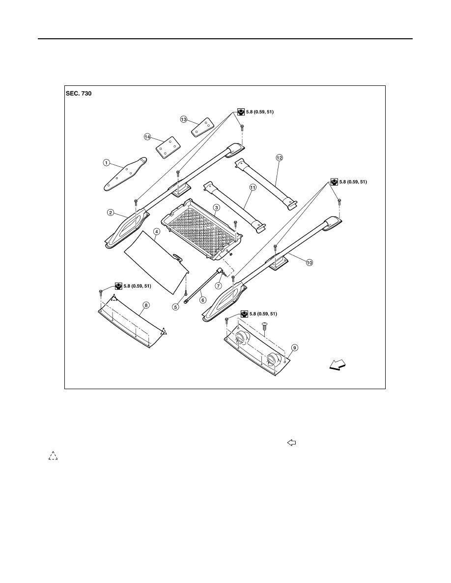
ROOF RACK
Removal and Installation
INFOID:0000000009483707
REMOVAL
1. Remove the front cover.
2. Remove storage bin and trim board as an assembly.
3. Remove front and rear crossbars (if equipped).
4. Remove side rails (LH/RH).
5. Remove front, center and rear stanchion gaskets.
INSTALLATION
Installation is in the reverse order of removal.
1.
Front stanchion gasket
2.
Side rail (RH)
3.
Storage bin (if equipped)
4.
Trim board
5.
Ball stud assembly
6.
Roof rack stay
7.
Ball stud assembly
8.
Front cover (except off-road)
9.
Front cover (off-road)
10. Side rail (LH)
11. Front crossbar (if equipped)
12. Rear crossbar (if equipped)
13. Rear stanchion gasket
14. Center stanchion gasket
Front
Clip C101
AWKIA1494GB