Nissan March K13. Manual - part 652


  Index      Nissan     Nissan March K13 - Service and Repair Manual)


Search            


Content   ..  650  651  652  653   ..


Nissan March K13. Manual - part 652


TRANSAXLE ASSEMBLY

TM-25

< UNIT DISASSEMBLY AND ASSEMBLY >

[5MT: RS5F91R]

C

E

F

G

H

I

J

K

L

M

A

B

TM

N

O

P

Disassembly

INFOID:0000000006056580

1.

Remove drain plug and gasket from clutch housing, using a socket [Commercial service tool] and drain
gear oil.

2.

Remove filler plug and gasket from transaxle case.

3.

Remove rear housing and O-ring.

CAUTION:

Remove to axial direction of input shaft (

) because rear

housing oil channel is inserted to input shaft center hole.
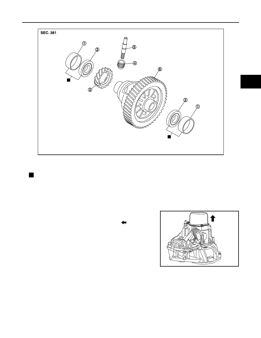
1.

Differential side bearing outer race

2.

Differential side bearing

3.

Speedometer drive gear

4.

Pinion gear

5.

Pinion shaft

6.

Final drive assembly

: Replace the parts as a set.

JPDIC0602ZZ

SCIA1709J

TM-26

< UNIT DISASSEMBLY AND ASSEMBLY >

[5MT: RS5F91R]

TRANSAXLE ASSEMBLY

4.

Shift the shifter lever A (1) to the 3rd gear position.
NOTE:
• If it is not shifted to the 3rd gear position, transaxle case can-

not be removed from clutch housing.

• The 3rd gear position means that shifter lever A is fully rotated

clockwise and it is returned approximately 10 degrees.

5.

Remove 5th-reverse shift fork (1) and 5th-reverse coupling
sleeve according to the following steps.

a.

Remove retaining pin from 5th-reverse shift fork, using a pin
punch (A).

b.

Press 5th-reverse shift fork, shift to 5th, and then engage it with
3rd gear.

c.

Remove mounting bolt (B).

d.

Remove mounting nut (C) and washer.

CAUTION:

Never use an impact wrench for removal, or otherwise each
gear may be damaged.

e.

Remove 5th-reverse shift fork and 5th-reverse coupling sleeve from 5th-reverse synchronizer hub.

6.

Remove 5th-reverse synchronizer hub from input shaft, using a
puller [Commercial service tool].

CAUTION:

Set claw of the puller to the wider side of the hub when set-
ting the puller in 5th-reverse synchronizer hub.

7.

Remove spread springs from 5th-reverse synchronizer hub.

8.

Remove 5th baulk ring, 5th input gear, bushing, and adapter
plate from input shaft.

9.

Remove 5th main gear from mainshaft, using the pullers.

PCIB1524E

JPDIC0532ZZ

PCIB1526E

A

: Puller [SST: KV32300QAC]

B

: Puller [SST: KV32300QAD]

PCIB1527E

TRANSAXLE ASSEMBLY

TM-27

< UNIT DISASSEMBLY AND ASSEMBLY >

[5MT: RS5F91R]

C

E

F

G

H

I

J

K

L

M

A

B

TM

N

O

P

10. Remove position switch from transaxle case.

11. Remove transaxle case mounting bolts (

).

12. Remove transaxle case from clutch housing.

13. Remove spacer (1) and 4th main gear (2) from mainshaft.

14. Remove 5th-reverse fork rod (1) according to the following

steps.

a.

Pull 5th-reverse fork rod up until it contacts claw (

) of reverse

gear assembly (2).

b.

Press gear portion of reverse gear assembly down, and then
remove 5th-reverse fork rod from clutch housing.

15. Remove 3rd-4th fork rod assembly (1), 3rd-4th coupling sleeve

(2), and input shaft assembly (3) according to the following
steps.

a.

Remove 4th baulk ring, insert keys, and springs from mainshaft.

b.

Pull gear of reverse gear assembly (4) up.

c.

Pull 1st-2nd fork rod (5) up, and then maintain the neutral posi-
tion.

d.

Remove 3rd-4th fork rod assembly, 3rd-4th coupling sleeve, and
input shaft assembly from clutch housing at the same time.

16. Remove retaining pin from 3rd-4th shift fork, using a pin punch.

PCIB1627E

JPDIC0610ZZ

PCIB1529E

PCIB1530E

PCIB1531E

TM-28

< UNIT DISASSEMBLY AND ASSEMBLY >

[5MT: RS5F91R]

TRANSAXLE ASSEMBLY

17. Remove 3rd-4th shift fork from 3rd-4th shift fork rod.

18. Remove lock pins (

) from clutch housing.

19. Remove 1st-2nd fork rod assembly (1) and mainshaft assembly

(2) from clutch housing at the same time.

20. Remove retaining pin from 1st-2nd shift fork, using a pin punch.
21. Remove 1st-2nd shift fork from 1st-2nd shift fork rod.

22. Remove retaining pin from reverse gear assembly, using a pin

punch.

23. Remove reverse gear assembly from clutch housing.

24. Remove final drive assembly (1) from clutch housing.
25. Remove pinion gear, pinion shaft, and speed sensor from clutch

housing.

26. Remove magnet and dowel pins (2) from clutch housing.

JPDIC0534ZZ

PCIB1532E

MCIB0033E

PCIB1533E


Content   ..  650  651  652  653   ..