Nissan March K13. Manual - part 650
AIR BREATHER HOSE
TM-17
< REMOVAL AND INSTALLATION >
[5MT: RS5F91R]
C
E
F
G
H
I
J
K
L
M
A
B
TM
N
O
P
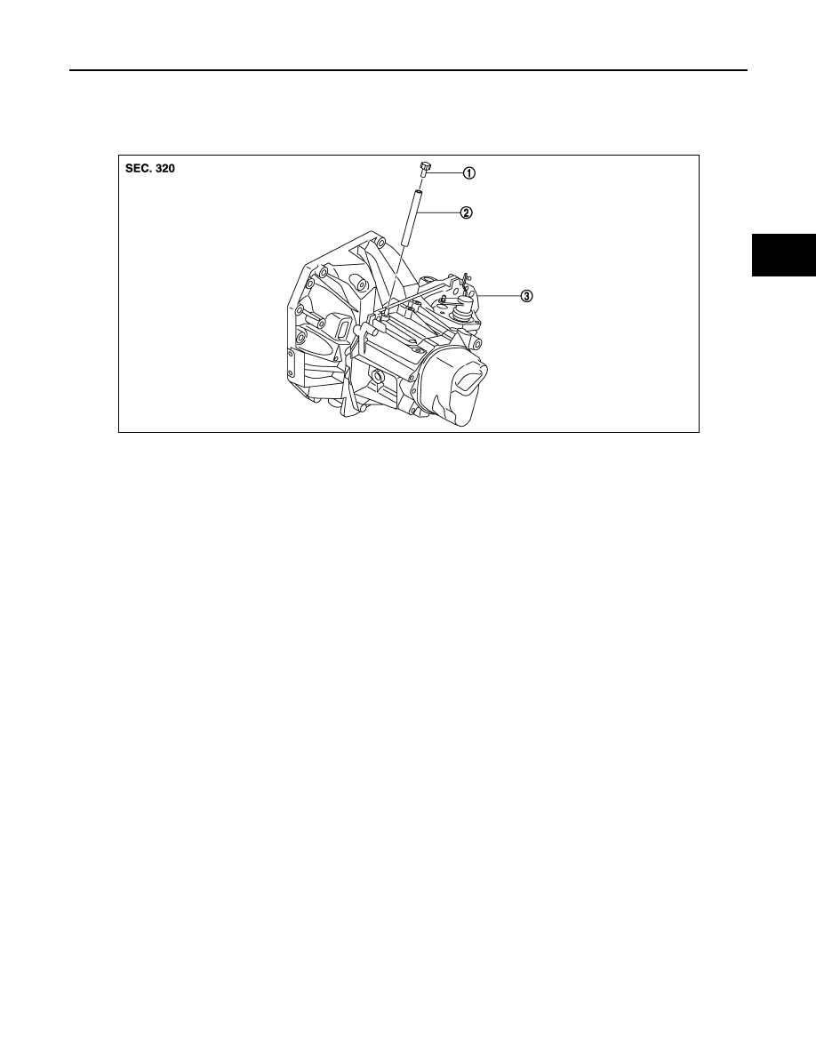
AIR BREATHER HOSE
Exploded View
INFOID:0000000006056573
Removal and Installation
INFOID:0000000006056574
REMOVAL
1.
Remove air breather hose from the 2 way connector.
CAUTION:
When removing air breather hose, be sure to hold 2 way connector securely.
2.
Remove cap hose from air breather hose.
INSTALLATION
Note the following, and install in the reverse order of removal.
CAUTION:
• Install air breather hose, preventing crush and clogging caused by bending.
• Insert the allowance of air breather hose to the spool of the 2 way connector.
1.
Cap
2.
Air breather hose
3.
2 way connector
JPDIC0788ZZ