Nissan March K13. Manual - part 649


  Index      Nissan     Nissan March K13 - Service and Repair Manual)


Search            


Content   ..  647  648  649  650   ..


Nissan March K13. Manual - part 649


SIDE OIL SEAL

TM-13

< REMOVAL AND INSTALLATION >

[5MT: RS5F91R]

C

E

F

G

H

I

J

K

L

M

A

B

TM

N

O

P

REMOVAL AND INSTALLATION

SIDE OIL SEAL

Removal and Installation

INFOID:0000000006056566

REMOVAL

1.

Remove front drive shafts. Refer to 

FAX-17, "Removal and Installation"

.

2.

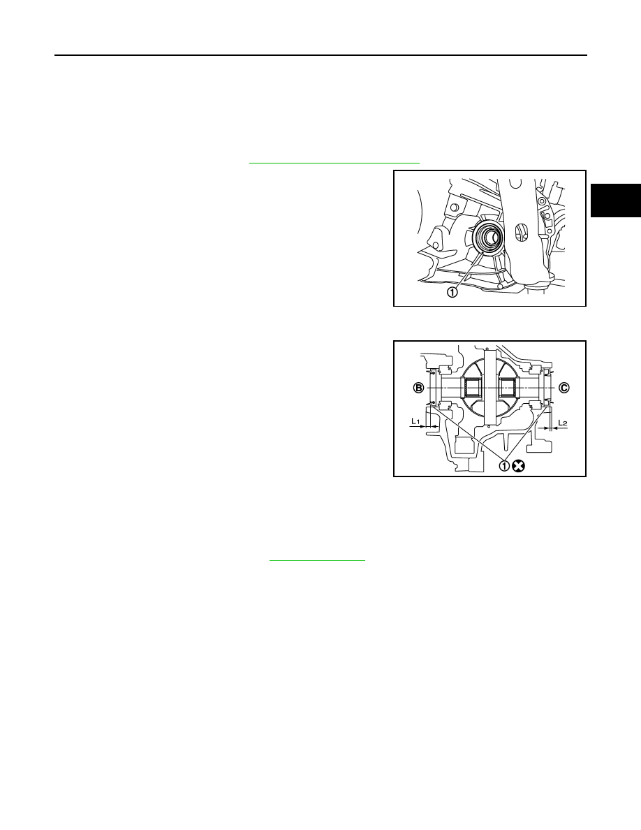
Remove differential side oil seals (1) from clutch housing and
transaxle case, using a suitable tool.

CAUTION:

Never damage transaxle case and clutch housing.

INSTALLATION

Note the following, and install in the reverse order of removal.
• Install differential side oil seals (1) to clutch housing and transaxle

case, using the drift [Stamping number: B.vi 1666-B] of the drift set
[SST: KV32500QAA].

CAUTION:

• Never incline differential side oil seal.
• Never damage clutch housing and transaxle case.

Inspection

INFOID:0000000006056567

INSPECTION AFTER INSTALLATION

Check the oil level and oil leakage. Refer to 

TM-12, "Inspection"

.

JPDIC0118ZZ

B

: Transaxle case side

C

: Clutch housing side

Dimension “L

1

: 5.7 – 6.3 mm (0.224 – 0.248 in)

Dimension “L

2

: 2.4 – 3.0 mm (0.094 – 0.118 in)

JPDIC0401ZZ

TM-14

< REMOVAL AND INSTALLATION >

[5MT: RS5F91R]

POSITION SWITCH

POSITION SWITCH

Removal and Installation

INFOID:0000000006056568

REMOVAL

1.

Drain gear oil. Refer to 

TM-12, "Draining"

.

2.

Disconnect position switch connector (A).

3.

Remove position switch from transaxle case.

INSTALLATION

1.

Apply recommended sealant to threads of position switch. 
• Use Genuine Liquid Gasket, Three Bond 1215 or an equivalent.

CAUTION:

Remove old sealant and oil adhering to threads.

2.

Install position switch to transaxle case.

3.

Tighten position switch to the specified torque. Refer to 

TM-21, "Exploded View"

.

4.

Refill gear oil. Refer to 

TM-12, "Refilling"

.

Inspection

INFOID:0000000006056569

INSPECTION AFTER INSTALLATION

• Check continuity between position switch terminals. Refer to 

TM-10, "BACK-UP LAMP SWITCH : Compo-

nent Inspection"

 (Back-up lamp switch) and 

TM-10, "PARK/NEUTRAL POSITION (PNP) SWITCH : Compo-

nent Inspection"

 (PNP switch).

• Check the oil leakage and the oil level. Refer to 

TM-12, "Inspection"

.

JPDIC0733ZZ

CONTROL LINKAGE

TM-15

< REMOVAL AND INSTALLATION >

[5MT: RS5F91R]

C

E

F

G

H

I

J

K

L

M

A

B

TM

N

O

P

CONTROL LINKAGE

Exploded View

INFOID:0000000006056570

Removal and Installation

INFOID:0000000006056571

REMOVAL 

1.

Shift the shifter lever to the neutral position.

2.

Remove air duct (inlet), air cleaner body assembly, and air cleaner cover assembly. Refer to 

EM-24,

"Removal and Installation"

.

3.

Pull out and disconnect the each cable from the shifter lever A and the selector lever, using a suitable
remover.

4.

While pressing the lock of the selector cable in the direction of
the arrow shown in the figure, remove the selector cable from
the cable mounting bracket.

5.

While pressing the lock of the shifter cable in the direction of the
arrow shown in the figure, remove the shifter cable from the
cable mounting bracket.

6.

Remove cable mounting bracket from clutch housing.

7.

Pull the shifter lever knob upward to remove.

8.

Remove center console assembly. Refer to 

IP-21, "Removal and

Installation"

.

9.

Pull out and disconnect the each cable from the control device,
using a suitable remover.

1.

Shifter lever A

2.

Selector lever

3.

Selector cable

4.

Shifter cable

5.

Cable mounting bracket

6.

Tapping bolt

7.

Bracket

8.

Grommet

9.

Control device

10. Shifter lever

11.

Shifter lever knob

Refer to 

GI-4, "Components"

 for the symbols in the figure.

JPDIC0789GB

JPDIC0793ZZ

TM-16

< REMOVAL AND INSTALLATION >

[5MT: RS5F91R]

CONTROL LINKAGE

10. While pressing the lock of the selector cable in the direction of

the arrow shown in the figure, remove the selector cable from
the control device.

11. While pressing the lock of the shifter cable in the direction of the

arrow shown in the figure, remove the shifter cable from the con-
trol device.

12. Remove the control device.

13. Remove center muffler, exhaust front tube, and heat plate. Refer

to 

EX-5, "Removal and Installation"

.

14. Remove the bracket from the vehicle.

15. Remove the grommet and then remove the shifter cable and

selector cable from the vehicle.

INSTALLATION

Note the following, and install in the reverse order of removal.

CAUTION:

• Install each cable without causing interference with other parts, a 120 mm (4.72 in)-or-less bend, and

a 180-degrees-or-more twist.

• Install boot of each cable without causing interference with other parts and a 90-degrees-or-more

twist.

• Fit boot of to center console assembly the groove on shifter lever knob.
• To install the shifter lever knob, press it into the shifter lever.

CAUTION:

• Never reuse shifter lever knob.
• Be careful with orientation of shifter lever knob.

• Tapping work for tapping bolts is not applied to new clutch housing. Do not perform tapping by other than

screwing tapping bolts because tapping is formed by screwing tapping bolts into clutch housing.

CAUTION:

Never reuse tapping bolt.

• Insert the each cable until it reaches the cable mounting bracket.
• Insert the each cable until it reaches the shifter lever A and the selector lever.
• Shift the shifter lever to the neutral position.

Inspection

INFOID:0000000006056572

INSPECTION AFTER INSTALLATION

Shifter lever knob

Check that the shifter lever knob is installed in the right position.

Shifter cable and selector cable

• Pull each cable in the removal direction to check that it dose not disconnect from the cable mounting

bracket.

• Pull each cable in the removal direction to check that it dose not disconnect from the control device.
• Pull grommet in the removal direction to check that it dose not disconnect from the vehicle.

Shifter lever

• Check that there is no tangle, hook, abnormal sound, looseness, and interference when the shifter lever is

moved to each position. If there is a malfunction, then repair or replace the malfunctioning part. 

• Check that the shifter lever smoothly returns to the neutral position after moving the lever from 1st to 2nd

gear and moving hands off the lever. If there is a malfunction, then repair or replace the malfunctioning part.

• Check that the shifter lever smoothly returns to the neutral position after moving the lever from 5th to the

reverse gear position and moving hands off the lever. If there is a malfunction, then repair or replace the mal-
functioning part.

JPDIC0793ZZ


Content   ..  647  648  649  650   ..