Nissan March K13. Manual - part 282


  Index      Nissan     Nissan March K13 - Service and Repair Manual)


Search            


Content   ..  280  281  282  283   ..


Nissan March K13. Manual - part 282


EM-62

< REMOVAL AND INSTALLATION >

[HR12DE]

CAMSHAFT

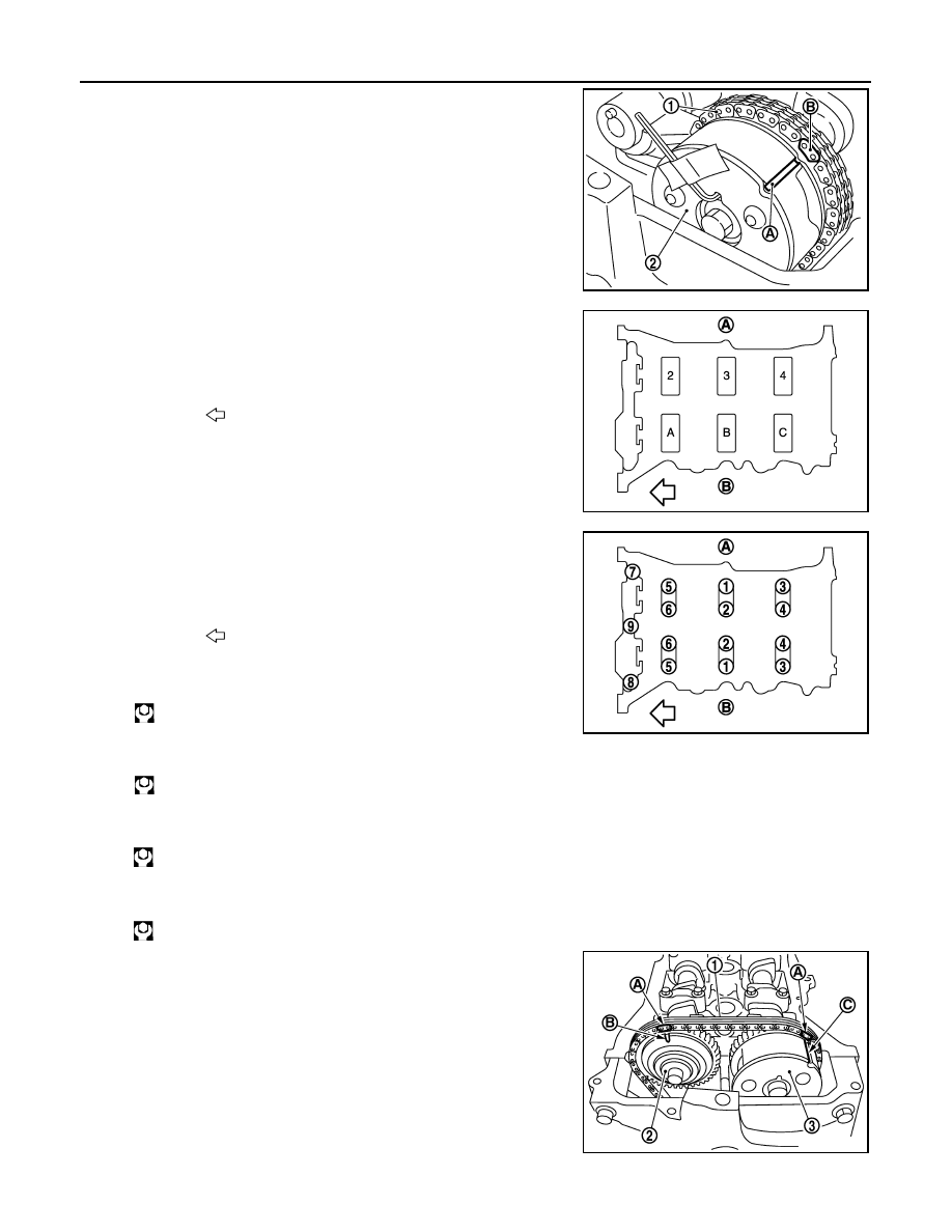
11. Install timing chain (1) by aligning its matching mark (marked

when timing chain is removed) (B) with matching mark (periph-
eral stamp line) (A) on camshaft sprocket (INT) (2).

12. Install camshaft brackets (No. 2 to 4) aligning the identification

marks on upper surface as shown in the figure.

• Install so that identification mark can be correctly read when

viewed from the INT side.

13. Tighten mounting bolts of camshaft brackets in the following

steps, in numerical order as shown in the figure.

a.

Tighten No. 7 to 9 in numerical order.

b.

Tighten No. 1 to 6 in numerical order.

c.

Tighten all bolts in numerical order.

d.

Tighten all bolts in numerical order.

14. Install the camshaft (EXH) to the camshaft sprocket (EXH) (2)

while aligning the matching mark (marked when timing chain is
removed) (A) and the matching mark (stamp) (B) of camshaft
sprocket (EXH).

• If the positions of knock pin and pin groove are not aligned,

move the camshaft (EXH) slightly to correct these positions.

PBIC3702E

A

: EXH side

B

: INT side

: Engine front

JPBIA3368ZZ

A

: EXH side

B

: INT side

: Engine front

: 2.0 N·m (0.2 kg-m, 1 ft-lb)

: 2.0 N·m (0.2 kg-m, 1 ft-lb)

: 5.9 N·m (0.6 kg-m, 4 ft-lb)

: 10.4 N·m (1.1 kg-m, 8 ft-lb)

1

: Timing chain 

3

: Camshaft sprocket (INT)

C

: Matching mark (peripheral stamp line)

JPBIA3369ZZ

PBIC3674E

CAMSHAFT

EM-63

< REMOVAL AND INSTALLATION >

[HR12DE]

C

D

E

F

G

H

I

J

K

L

M

A

EM

N

P

O

15. Tighten the mounting bolt.

CAUTION:

• Hold the camshaft hexagonal part (A), and then secure the

camshaft.

• Check that the matching mark (marked when timing chain

is removed) and each camshaft sprocket matching mark
are in the correct location.

16. Pull out the stopper pin (A), and then apply the tension to the

timing chain by rotating the crankshaft pulley clockwise slightly.

17. Install the plug (2) to the front cover (1).

• Apply liquid gasket to the threads, and tighten them. 
Use Genuine Liquid Gasket or equivalent.

18. Return the camshaft sprocket (INT) in the most retarded position with the following procedure.

a.

Remove the stopper pin (A) from the camshaft sprocket (INT).

1

: Camshaft sprocket (EXH)

JPBIA3397ZZ

1

: Plunger

2

: Chain tensioner

B

:  Lever

C

:  Lever  hole

D

: Front cover has been omitted

PBIC3772E

PBIC3675E

B

:  Tape

PBIC3685E

EM-64

< REMOVAL AND INSTALLATION >

[HR12DE]

CAMSHAFT

b.

Turn the crankshaft pulley (1) slowly clockwise (A) and return
the camshaft sprocket (INT) to the most retarded angle position.

• When first turning the crankshaft the camshaft sprocket (INT)

will turn. Once it is turned more, and the vane (camshaft) also
turns, then it has reached the most retarded angle position.

• The most retarded angle position can be checked by seeing if

the stopper pin groove (A) is shifted clockwise.

• After spinning the crankshaft slightly in the counterclockwise

direction, you can check the lock pin has joined by seeing if
the vane (camshaft) and the sprocket move together.

19. Install the camshaft position sensor (PHASE) to the rear end of cylinder head.

• Tighten bolts with it seated completely.

20. Check and adjust valve clearance. Refer to 

EM-11, "Inspection and Adjustment"

.

21. Install in the reverse order of removal.

Inspection

INFOID:0000000005988197

INSPECTION AFTER REMOVAL

Oil Filter

• Check that there is no foreign material on the oil filter (1) and check

it for clogging.

• Check the oil filter for damage.
• If there is some damage, replace the oil filter, the plug, and the

washer as a set.

Camshaft Runout

1.

Put V-block on a precise flat table, and support No. 2 and 5 jour-
nals of camshaft.

CAUTION:

Never support No. 1 journal (on the side of camshaft
sprocket) because it has a different diameter from the other
four locations.

2.

Set a dial indicator vertically to No. 3 journal.

3.

Turn camshaft to one direction with hands, and measure the
camshaft runout on the dial indicator. (Total indicator reading)

PBIC3704E

B

: Stopper pin hole

C

: Most advanced angle

D

: Lock pin engaged 

PBIC3705E

PBIC3693E

JPBIA3410ZZ

CAMSHAFT

EM-65

< REMOVAL AND INSTALLATION >

[HR12DE]

C

D

E

F

G

H

I

J

K

L

M

A

EM

N

P

O

4.

If it exceeds the limit, replace camshaft.

Camshaft Cam Height

1.

Measure the camshaft cam height with a micrometer (A).

2.

If wear exceeds the limit, replace camshaft.

Camshaft Journal Oil Clearance

CAMSHAFT JOURNAL DIAMETER
Measure the outer diameter of camshaft journal with a micrometer
(A).

CAMSHAFT BRACKET INNER DIAMETER
• Tighten camshaft bracket bolts with the specified torque. Refer to “INSTALLATION” for the tightening proce-

dure.

• Measure inner diameter (B) of camshaft bracket with a bore gauge

(A).

CAMSHAFT JOURNAL OIL CLEARANCE
• (Oil clearance) = (Camshaft bracket inner diameter) – (Camshaft journal diameter)

• If it exceeds the limit, replace either or both camshaft and cylinder head.

NOTE:
Camshaft brackets cannot be replaced as single parts, because they are machined together with cylinder
head. Replace whole cylinder head assembly.

Camshaft End Play

Standard and Limit

: Refer to 

EM-93, "Camshaft"

.

Standard and Limit

Intake

: Refer to 

EM-93, "Camshaft"

.

Exhaust

Cam wear limit:

: Refer to 

EM-93, "Camshaft"

.

PBIC3178J

Standard:

: Refer to 

EM-93, "Camshaft"

.

PBIC3179J

Standard

: Refer to 

EM-93, "Camshaft"

.

PBIC3180J

Standard and Limit

: Refer to 

EM-93, "Camshaft"

.


Content   ..  280  281  282  283   ..