Nissan March K13. Manual - part 280


  Index      Nissan     Nissan March K13 - Service and Repair Manual)


Search            


Content   ..  278  279  280  281   ..


Nissan March K13. Manual - part 280


EM-54

< REMOVAL AND INSTALLATION >

[HR12DE]

CAMSHAFT

1.

Support the bottom surface of engine using a transmission jack, and then remove the engine mounting
bracket and insulator (RH). Refer to 

EM-79, "Exploded View"

.

2.

Remove rocker cover. Refer to 

EM-41, "Exploded View"

.

3.

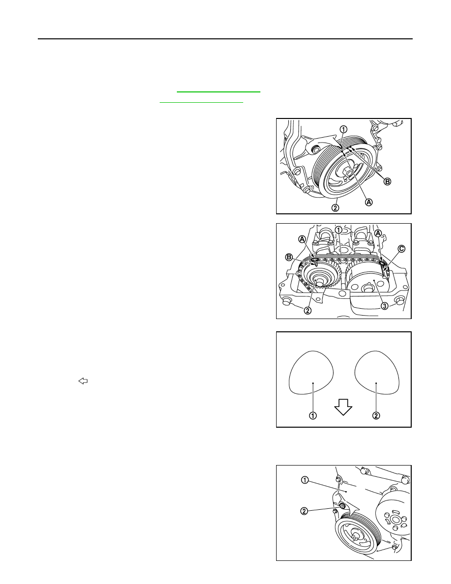
Place cylinder No. 1 at TDC with the following procedure.

a.

Rotate crankshaft pulley (2) clockwise and align TDC mark
(without paint mark) (A) to timing indicator (1) on front cover.

b.

Check that the matching marks on each camshaft sprocket are
in the position as shown in the figure.

• If the matching marks are not in place, rotate crankshaft pull

one more turn to satisfy the position shown in figure.

c.

Check that the cam nose of cylinder 1 is positioned as shown in
the figure.

d.

Paint matching marks (A) on the timing chain links

4.

Secure the plunger of chain tensioner in the fully compressed position with the following procedure. And
then, loosen the timing chain tension.

a.

Remove the plug (2) from the front cover (1).

·Step 9

: The camshaft (EXH) can be removed simultaneously with the camshaft (INT).

·Step 10

: When the camshaft sprocket (INT) mounting bolt is removed, the lifting up of cam-
shaft is not necessary.

B

: White paint mark (Not use for service)

PBIC3673E

1.

: Timing chain 

2.

: Camshaft sprocket (EXH)

3.

: Camshaft sprocket (INT)

A

: Matching mark (Paint)

B

: Matching mark (Stamp)

C

: Matching mark (Peripheral stamp line)

1.

: Camshaft (EXH)

2.

: Camshaft (INT)

: Cylinder head side

PBIC3674E

JPBIA3413ZZ

PBIC3675E

CAMSHAFT

EM-55

< REMOVAL AND INSTALLATION >

[HR12DE]

C

D

E

F

G

H

I

J

K

L

M

A

EM

N

P

O

b.

Fully push down the lever (B) of chain tensioner (2) from the
plug hole, and then insert the stopper pin (A) into the body side
hole and secure the lever at the lowest position.

• The tab is released by fully pushing the lever down. As a

result, the plunger (1) can be moved.

NOTE:
Hexagonal wrench [2.5 mm (0.098 in)] is used for a stopper pin
as an example.

CAUTION:

The stopper pin must use a shape that cannot fall in the
front cover when dropping out. 

c.

Turn the crankshaft pulley (2) counterclockwise with the cam-
shaft (EXH) (1) fixing. Apply the tension to the timing chain, and
then push the plunger of into the inside of chain tensioner.

CAUTION:

Hold the camshaft hexagonal part (A), and then secure the
camshaft.

d.

Pull out the stopper pin (A) of chain tensioner (2) side from plug
hole. Lift the lever (B) up to align its hole position with the hole of
the body.

• When the lever hole (C) is aligned with the body hole position,

the plunger (1) is fixed.

• When the protrusion parts of the plunger ratchet and the tab

face each other, both hole positions are not aligned. At that
time, correctly engage them and align these hole positions by
slightly moving the plunger.

e.

Insert the stopper pin into the body hole through the lever hole, and then fix the lever at the upper position.

f.

Slightly rotate the crankshaft pulley (2) clockwise to loosen the
timing chain on camshaft sprocket (EXH) (1) side.

CAUTION:

Hold the camshaft hexagonal part (A), and then secure the
camshaft.

C : Front cover has been omitted

PBIC3676E

PBIC3677E

D : Front cover has been omitted

PBIC3772E

PBIC3773E

EM-56

< REMOVAL AND INSTALLATION >

[HR12DE]

CAMSHAFT

5.

Remove camshaft sprocket (EXH) (1).

CAUTION:

• Hold the camshaft hexagonal part (A), and then secure the

camshaft.

• Never rotate crankshaft and camshaft separately, so as

not to contact valve with piston in the following steps.

NOTE:
The timing chain with the front cover installed is not disengaged
from the crankshaft sprocket and it is not dropped into the front
cover. Therefore, the timing chain tension holding device is not
necessary.

6.

Turn the camshaft sprocket (INT) to the most advanced position.

CAUTION:

Installation and removal of the camshaft sprocket (INT) must be done in the most advanced posi-
tion for the following reasons, so check that you follow the procedure exactly.
• The sprocket (C) and vane (camshaft coupling) (B) are

designed to spin and move within the range of a certain
angle.

• With the engine stopped and the vane in the most

retarded angle, it will not spin because it is locked to the
sprocket side by the internal lock pin (A).

• If the camshaft sprocket mounting bolts are turned in the

situation described above, the lock pin will become dam-
aged and cause malfunctions because of the increased
horizontal load (cutting force) on the lock pin.

• Put the camshaft sprocket (INT) in the most advance position with the following procedure.

a.

Remove camshaft bracket (No. 1) (1).

• Loosen the bolts in several steps, and then remove them.

b.

Apply the following air pressure to the No. 1 journal oil hole (A)
of camshaft (INT) (1) shown in the figure using an air gun.

• Apply the air pressure into the oil hole on the second groove

from the front of camshaft thrust (B).

• Proceed all the way through step “e” with the air pressure on.

JPBIA3397ZZ

PBIC3679E

: Engine front

PBIC3680E

Pressure

: 300 kPa (3.0 bar, 3.1 kg/cm

2

, 44psi) or more

PBIC3681E

CAMSHAFT

EM-57

< REMOVAL AND INSTALLATION >

[HR12DE]

C

D

E

F

G

H

I

J

K

L

M

A

EM

N

P

O

• Attach the rubber nozzle (B) narrowed to the top of the air gun

(A) to prevent air leakage from the oil hole. Securely apply the
air pressure to the oil hole.

CAUTION:

• There are other oil holes in the side grooves. Never use

the incorrect oil holes.

• Be sure not to damage the oil path with the tip of the air

gun.

• Wipe all the oil off the air gun to prevent oil from being

blown all over along with the air, and the area around the
air gun should be wiped with a rag when applying air
pressure. Eye protection should be worn as needed.

NOTE:
The air pressure is used to move the lock pin into the disengage position.

c.

Hold the camshaft sprocket (INT) with hands, and then apply the power counterclockwise/clockwise alter-
natively.
• Finally rotate the sprocket of the camshaft sprocket (INT) counterclockwise [the direction shown by the

arrow (

)].

• Perform the work while applying the air pressure to the oil hole.
• If the lock pin is not released by hands, tap the camshaft

sprocket (INT) lightly with a plastic hammer (A).

• If the camshaft sprocket (INT) is not rotated counterclockwise

even if the above procedures are performed, check the air
pressure and the oil hole position.

d.

While doing the above, once you hear a click (the sound of the
internal lock pin disengaging) from inside the camshaft sprocket
(INT), start turning the camshaft sprocket (INT) in the counter-
clockwise direction in the most advanced angle position.

• Keep the air pressure on.
• If there is no click, as soon as the vane-side (camshaft side)

starts moving independently of the sprocket, the lock pin has
become disengaged.

• Check that it is in the most advanced angle position by seeing

if the stopper pin groove (A) and the stopper pin hole (B) are matched up as shown in the figure.

e.

Complete the applying procedure of air pressure and the holding procedure of camshaft (INT).

f.

Insert the stopper pin (A) into the stopper pin holes in the cam-
shaft sprocket (INT) and lock in the most advanced angle posi-
tion.

CAUTION:

No load is exerted on the stopper pin (spring reaction, etc.).
Since it comes out easily, secure it with tape (B) to prevent
it from coming out.
NOTE:
The stopper pin in the figure shows one example of a hexagonal
wrench for 2.5 mm (0.098 in) [length of inserted section:
approximately15 mm (0.59 in)].

7.

Remove camshaft brackets (No. 2 to 5).

PBIC3682E

PBIC3683E

C

: Lock pin engaged 

D

: Most advanced angle

PBIC3684E

PBIC3685E


Content   ..  278  279  280  281   ..