Nissan March K13. Manual - part 281


  Index      Nissan     Nissan March K13 - Service and Repair Manual)


Search            


Content   ..  279  280  281  282   ..


Nissan March K13. Manual - part 281


EM-58

< REMOVAL AND INSTALLATION >

[HR12DE]

CAMSHAFT

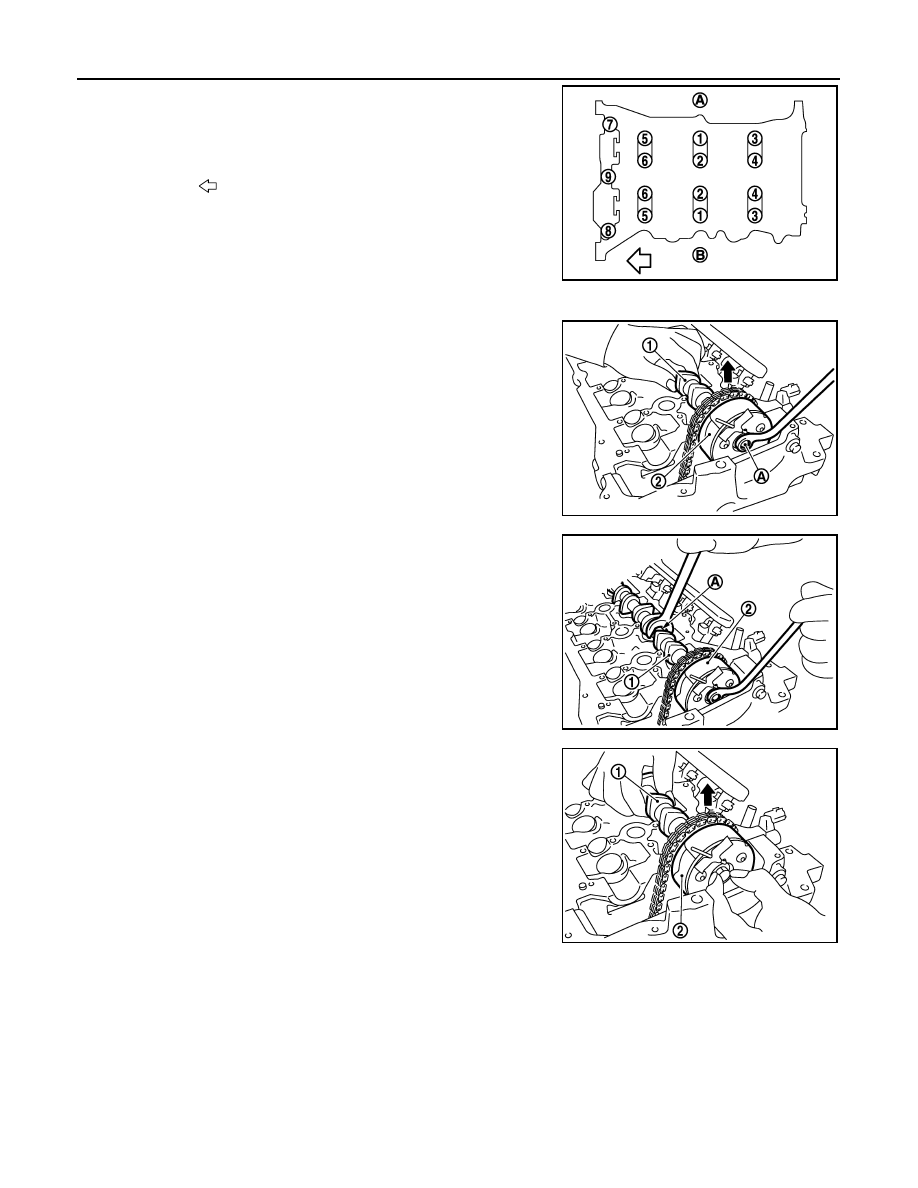
• Loosen bolts in several steps in the reverse of the order as

shown in the figure.

NOTE:
The camshaft bracket (No. 1) has been already removed.

8.

Remove camshaft (EXH).

9.

Remove the camshaft (INT) (1) and the camshaft sprocket (INT)
(2) with the following procedure.

a.

Lift up the camshaft sprocket (INT), and then set the thin tools (a
box wrench, etc.) to the mounting bolt (A).

b.

Return the camshaft (INT) to the cylinder head journal quietly.

c.

Keeping the camshaft hexagonal part (A) still with the wrench,
loosen mounting the bolts for the camshaft sprocket (INT) (2).

d.

Lift up the camshaft (INT) (1), and then disassemble the cam-
shaft from the camshaft sprocket (INT) (2).

e.

Remove camshaft (INT) rearward.

CAUTION:

Never damage the signal plate of rear end.

A

: EXH side

B

: INT side

: Engine front

JPBIA3369ZZ

PBIC3687E

1.

Camshaft (INT)

JPBIA3398ZZ

PBIC3689E

CAMSHAFT

EM-59

< REMOVAL AND INSTALLATION >

[HR12DE]

C

D

E

F

G

H

I

J

K

L

M

A

EM

N

P

O

f.

Remove camshaft sprocket (INT) (1).

CAUTION:

Never drop stopper pin.

CAUTION:

• Tape (C) the stopper pin (B) so it does not come out.
• Never subject it to impact by dropping.
• Never disassemble. [Never loosen the three mounting

bolts (A)].

NOTE:
While removing the camshaft sprocket (INT), if you have taken
out the stopper pin and the lock pin has been rejoined in the
most retarded angle, do the following to restore it.

i.

Install the camshaft (INT) and tighten the mounting bolts enough to prevent air from leaking out.

CAUTION:

The internal lock pin will get damaged, so keep the torque on the mounting bolts to the minimum
required to prevent air from escaping.

ii.

Apply the air pressure, disengage the lock pin, and turn the vane to the most advanced angle position.

iii.

Insert the stopper pin.

iv.

Remove camshaft sprocket (INT) from the camshaft.

10. Remove valve lifter.

• Identify installation positions, and store them without mixing them up.

11. Remove intake valve timing control solenoid valve (1).
12. Remove the alternator and bracket, remove the plug (2), and

then remove the oil filter. Refer to 

CHG-27, "Removal and Instal-

lation"

.

INSTALLATION

PBIC3690E

PBIC3691E

PBIC3692E

EM-60

< REMOVAL AND INSTALLATION >

[HR12DE]

CAMSHAFT

1.

Install the oil filter (1).

• The oil filter is assembled to the plug (3), and then install it to

the cylinder head.

2.

Install intake valve timing control solenoid valve.
• Insert it straightly into the cylinder head.
• Tighten bolts after placing it completely.

3.

Install valve lifter.
• If it is reused, install in its original positions.

4.

Put a matching mark for positioning the camshaft (INT) and the camshaft sprocket (INT) with the following
procedure.
NOTE:
It prevents the knock pin from engaging with the incorrect pin hole after installing the camshaft (INT) and
the camshaft sprocket (INT).

a.

Put the matching marks (A) on a line extending from the knock
pin position of camshaft (INT) (1) front surface.
• Put the marks on the visible position with the camshaft

sprocket installed. (The figure shows an example.)

b.

Put the matching marks on a line extending from the knock pin
hole (B) position of camshaft sprocket (INT) (2). (The figure
shows an example.)
• Put the marks on the visible position with it installed to the

camshaft.

5.

Set the camshaft sprocket (INT) to between cylinder head and
front cover.
• Set it with the knock pin hole (A) facing up.

CAUTION:

Check the stopper pin is inserted at the most advanced
position beforehand.

6.

Install camshaft.

• Distinction between camshaft (INT and EXH) is performed with

the different shapes of rear end.

2

:  Washer

PBIC3695E

PBIC3696E

PBIC3697E

1

: Camshaft (EXH)

2

: Camshaft (INT)

A

: Identification mark

JPBIA3396ZZ

CAMSHAFT

EM-61

< REMOVAL AND INSTALLATION >

[HR12DE]

C

D

E

F

G

H

I

J

K

L

M

A

EM

N

P

O

• Install camshafts to the cylinder head so that knock pins (A) on

front end are positioned as shown in the figure.

NOTE:
Though camshaft does not stop at the portion as shown in the
figure, for the placement of cam nose, it is generally accepted
camshaft is placed for the same direction of the figure.

7.

Install the camshaft sprocket (INT) to the camshaft (INT) with the
following procedure.

a.

Refer to the matching mark (A) put according to step “4”.
Securely align the knock pin and the pin hole, and then install
them.

b.

Lift up the front side of camshaft (INT) (1), and then temporarily
tighten the bolt.

8.

Put a thick shop cloth (B) to the lower surface, and then set the
tools to the bolt while lifting up the front side of camshaft (INT)
(1).

9.

Tighten the mounting bolt.

CAUTION:

Hold the camshaft hexagonal part (A), and then secure the
camshaft.

10. Return the camshaft (INT) to the cylinder head quietly.

1

: Camshaft (EXH)

2

: Camshaft (INT)

: Upper side

PBIC3699E

PBIC3700E

2

: Camshaft sprocket (INT)

PBIC3689E

JPBIA3399ZZ


Content   ..  279  280  281  282   ..