Nissan March K13. Manual - part 275
EM-34
< REMOVAL AND INSTALLATION >
[HR12DE]
OIL PAN (LOWER)
OIL PAN (LOWER)
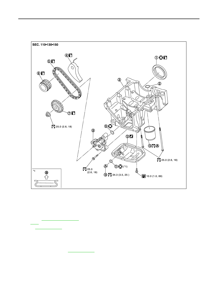
Exploded View
INFOID:0000000005988184
Removal and Installation
INFOID:0000000005988185
REMOVAL
1.
Drain engine oil. Refer to
.
2.
Remove oil pan (lower) with the following procedure:
1.
Rear oil seal
2.
O-ring
3.
Oil pan (upper)
4.
Oil pump chain tensioner
5.
Oil pump drive chain
6.
Crankshaft sprocket
7.
Oil pump sprocket
8.
Oil pump
9.
O-ring
10. Drain plug
11.
Drain plug washer
12. Oil pan (lower)
13. Oil filter
A.
B.
Oil pan (lower) side
Refer to
for symbols in the figure.
JPBIA3384GB