Nissan March K13. Manual - part 273
EM-26
< REMOVAL AND INSTALLATION >
[HR12DE]
EGR SYSTEM
EGR SYSTEM
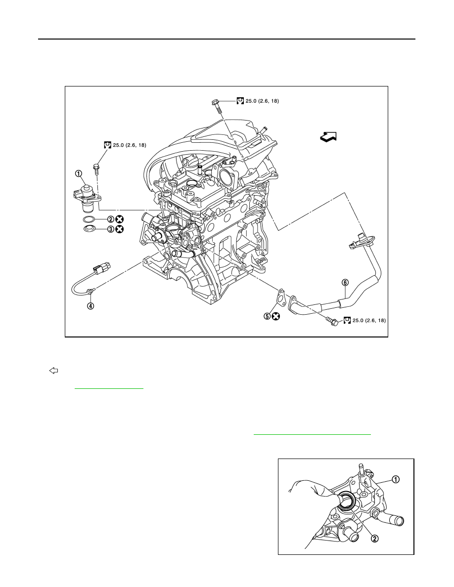
Exploded View
INFOID:0000000006038725
• Refer to
for symbol marks except in the above.
Removal and Installation
INFOID:0000000006038726
REMOVAL
1.
Remove air duct (inlet) and air cleaner assembly. Refer to
EM-24, "Removal and Installation"
.
2.
Remove EGR guide tube.
3.
Remove EGR volume control valve.
• Remove holder (2) from water outlet (1) if removed from EGR
volume control valve.
CAUTION:
• Do not damage or impact EGR volume control valve.
• Do not disassemble or adjust EGR volume control valve.
1.
EGR volume control valve
2.
O-ring
3.
Holder
4.
EGR temperature sensor
5.
Gasket
6.
EGR guide tube
Engine front
JPBIA3414GB
JPBIA3462ZZ