Nissan March K13. Manual - part 272
EM-22
< PERIODIC MAINTENANCE >
[HR12DE]
SPARK PLUG
SPARK PLUG
Removal and Installation
INFOID:0000000005988173
REMOVAL
1.
Remove ignition coil. Refer to
.
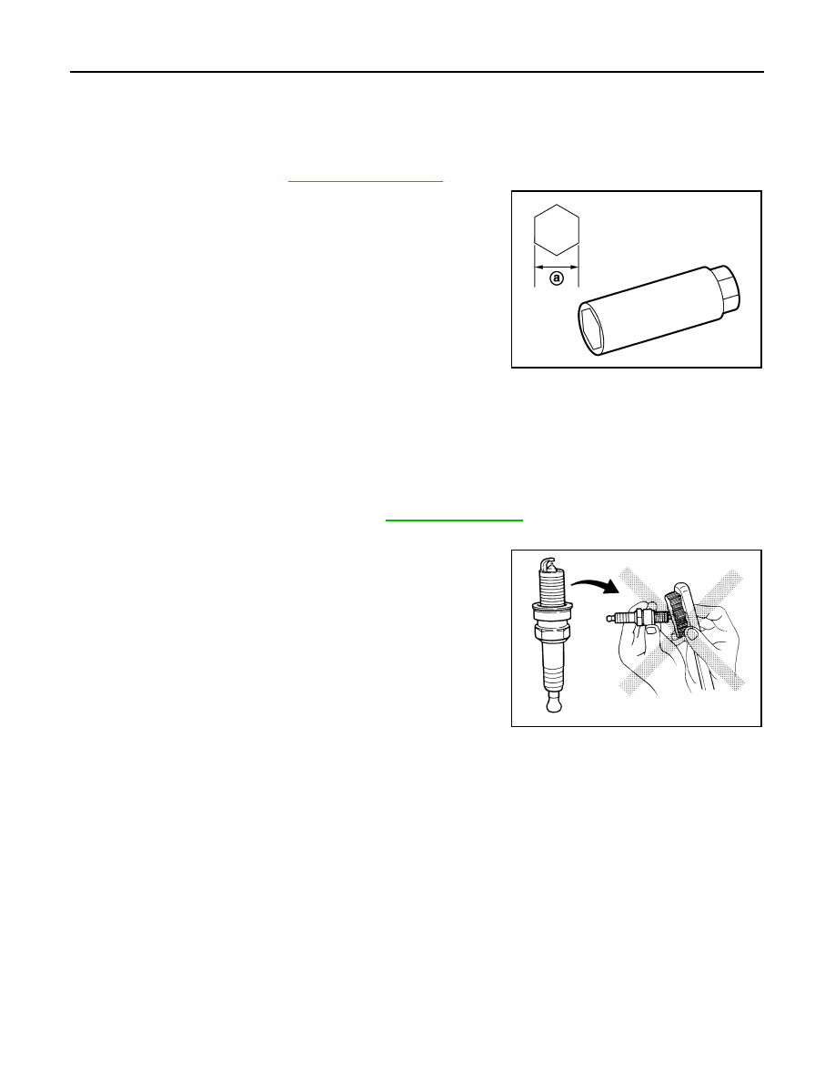
2.
Remove spark plug with a spark plug wrench (commercial ser-
vice tool).
CAUTION:
Never drop or shock spark plug.
INSTALLATION
Install in the reverse order of removal.
Inspection
INFOID:0000000005988174
INSPECTION AFTER REMOVAL
Use the standard type spark plug for normal condition.
CAUTION:
• Never drop or shock spark plug.
• Never use a wire brush for cleaning.
• If plug tip is covered with carbon, spark plug cleaner may be
used.
a
: 14 mm (0.55 in)
JPBIA0030ZZ
Spark plug (Standard type)
: Refer to
Cleaner air pressure
: Less than 588 kPa (6 kg/cm
2
,
85 psi)
Cleaning time
: Less than 20 seconds
SMA773C