Nissan March K13. Manual - part 271


  Index      Nissan     Nissan March K13 - Service and Repair Manual)


Search            


Content   ..  269  270  271  272   ..


Nissan March K13. Manual - part 271


EM-18

< PERIODIC MAINTENANCE >

[HR12DE]

DRIVE BELT

PERIODIC MAINTENANCE

DRIVE BELT

Checking

INFOID:0000000005988168

• Inspection should be done only when engine is cold or over 30

minutes after the engine is stopped.

• Visually check belts for wear, damage, and cracks on inside and

edges.

• Turn crankshaft pulley two time clockwise, and check tension on all pulleys is equal before doing the test.
• When measuring deflection, apply 98 N (10 kg, 22 lb) at the ( ) marked point.
• Measure the belt tension and frequency with acoustic tension gauge (commercial service tool) at the ( )

marked point.

CAUTION:

• When the tension and frequency are measured, the acoustic tension gauge should be used.
• When checking immediately after installation, first adjust it to the specified value. Then, after turning

crankshaft two turns or more, readjust to the specified value to avoid variation in deflection between
pulleys.

Tension Adjustment

INFOID:0000000005988169

CAUTION:

• When belt is replaced with new one, adjust belt tension to the value for “New belt”, because new belt

will not fully seat in the pulley groove.

• When tension of the belt being used exceeds “Limit”, adjust it to the value for “After adjusted”.
• When installing a belt, check it is correctly engaged with the pulley groove.
• Never allow oil or engine coolant to get on the belt.
• Never twist or bend the belt strongly.

1.

Remove front fender protector (RH). Refer to 

EXT-17, "FENDER PROTECTOR : Exploded View"

.

2.

Loosen the idler pulley lock nut (A) from the tightening position
with the specified torque by 45 degrees.

CAUTION:

• When the lock nut is loosened excessively, the idler pulley tilts and the correct tension adjust-

ment cannot be performed. Never loosen it excessively (more than 45 degrees).
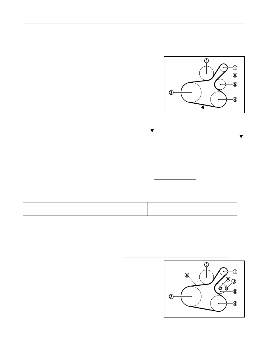
1

:  Alternator

2

:  Water  pump

3

: Crankshaft pulley

4

: A/C compressor (With A/C models)
: Idler pulley (Without A/C models)

5

: Idler pulley

6

:  Drive  belt

Belt Deflection/Belt Tension and Frequency: Refer to 

EM-92, "Drive Belt"

.

PBIC3642E

Location

Location of adjuster and tightening method

Drive belt

Adjusting bolt on idler pulley

1

:  Alternator

2

:  Water  pump

3

: Crankshaft pulley

4

: A/C compressor (with A/C models)
: Idler pulley (without A/C models)

5

: Idler pulley

6

: Drive belt

PBIC3643E

DRIVE BELT

EM-19

< PERIODIC MAINTENANCE >

[HR12DE]

C

D

E

F

G

H

I

J

K

L

M

A

EM

N

P

O

• Put a matching mark on the lock nut (A), and check turning angle with a protractor. Never visu-

ally check the tightening angle.

3.

Adjust the belt tension by turning the adjusting bolt (B). Refer to 

EM-18, "Checking"

.

CAUTION:

• When checking immediately after installation, first adjust it to the specified value. Then, after

turning crankshaft two turns or more, readjust to the specified value to avoid variation in deflec-
tion between pulleys.

• When the tension adjustment is performed, the lock nut should be in the condition at step“ 2”. If

the tension adjustment is performed when the lock nut is loosened more than the standard, the
idler pulley tilts and the correct tension adjustment cannot be performed.

4.

Tighten the lock nut.

Removal and Installation

INFOID:0000000005988170

REMOVAL

1.

Remove front fender protector (RH). Refer to 

EXT-17, "FENDER PROTECTOR : Exploded View"

.

2.

Loosen the lock nut (A), and then adjust the belt tension by turn-
ing the adjusting bolt (B).

3.

Remove drive belt.

INSTALLATION

1.

Pull the idler pulley in the loosening direction, and then tempo-
rarily tighten the lock nut (A) to the following torque.

NOTE:
Do not move the lock nut from the tightened position. Go to step “2”.

2.

Install the drive belt to each pulley.

CAUTION:

• Check that there is no oil, grease, or coolant, etc. in pulley grooves.
• Check that the belt is securely inside the groove on each pulley.

3.

Adjust drive belt tension by turning the adjusting bolt (B). Refer to 

EM-18, "Tension Adjustment"

.

CAUTION:

• Perform the belt tension adjustment with the lock nut temporarily tightened at the step “1” so as

not to tilt the idler pulley.

: 34.8 N·m (3.5 kg-m, 26 ft-lb)

1

:  Alternator

2

:  Water  pump

3

: Crankshaft pulley

4

: A/C compressor (with A/C models)
: Idler pulley (without A/C models) 

5

: Idler pulley

6

:  Drive  belt

PBIC3643E

1

:  Alternator

2

:  Water  pump

3

: Crankshaft pulley

4

: A/C compressor (with A/C models)
: Idler pulley (without A/C models) 

5

: Idler pulley

6

:  Drive  belt

: 4.4 N·m (0.45 kg-m, 39 in-lb)

PBIC3643E

EM-20

< PERIODIC MAINTENANCE >

[HR12DE]

DRIVE BELT

• When checking immediately after installation, first adjust it to the specified value. Then, after

turning crankshaft two turns or more, readjust to the specified value to avoid variation in deflec-
tion between pulleys.

4.

Tighten the lock nut.

5.

Check that belt tension of each belt within the standard.

: 34.8 N·m (3.5 kg-m, 26 ft-lb)

AIR CLEANER FILTER

EM-21

< PERIODIC MAINTENANCE >

[HR12DE]

C

D

E

F

G

H

I

J

K

L

M

A

EM

N

P

O

AIR CLEANER FILTER

Exploded View

INFOID:0000000005988171

Removal and Installation

INFOID:0000000005988172

REMOVAL

1.

Remove air duct (inlet).

2.

Remove air cleaner body assembly (2) with air cleaner filter (1).

INSTALLATION

Install in the reverse order of removal.

1.

Mounting rubber

2.

Air duct (inlet)

3.

Air cleaner body assembly

4.

Air cleaner filter

5.

Air cleaner cover assembly

6.

Mass air floe sensor

7.

Clamp

8.

Air duct 

9.

Clamp

A.

To electric throttle control actuator

Refer to

GI-4, "Components"

 for symbols in the figure.

JPBIA3386GB

JPBIA3370ZZ


Content   ..  269  270  271  272   ..