Nissan March K13. Manual - part 276
EM-38
< REMOVAL AND INSTALLATION >
[HR12DE]
FUEL INJECTOR AND FUEL TUBE
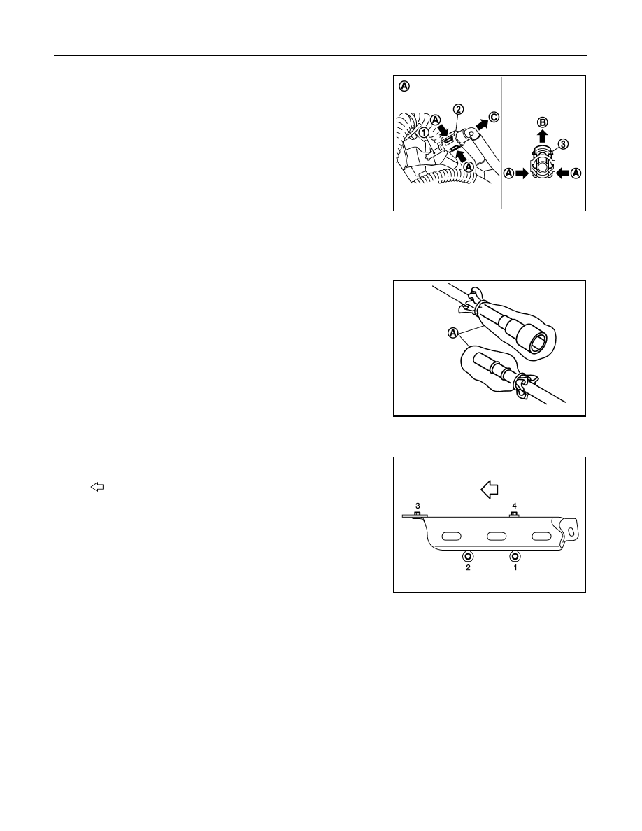
b.
Disconnect fuel feed hose from hose clamp.
c.
Disengage (C) and pull up (B) the pawl (A) of the quick connec-
tor retainer (3) by hand to disconnect quick connector (2) from
the fuel tube.
NOTE:
If the fuel tube connector is stuck, hold the fuel pipe by hand and
disconnect it by pushing and pulling.
CAUTION:
• Never pull with lateral force applied. O-ring inside quick
connector may be damaged.
• Prepare container and cloth beforehand as fuel will leak-
age out.
• Avoid fire and sparks.
• Keep parts away from heat source. Especially, be careful when welding is performed around
them.
• Never expose parts to battery electrolyte or other acids.
• Never bend or twist connection between quick connector and fuel feed tube during installation/
removal.
• To keep clean the connecting portion and to avoid dam-
age and foreign materials, cover them completely with
plastic bags, etc. (A) or something similar.
6.
Disconnect harness connector from fuel injector.
7.
Remove fuel tube protector.
• Loosen mounting bolts in reverse order as shown in the figure.
8.
Remove fuel tube and fuel injector assembly.
CAUTION:
• When removing, be careful to avoid any interference with fuel injector.
• Use a shop cloth to absorb any fuel leakage from fuel tube.
9.
Remove fuel injector from fuel tube with the following procedure:
JPBIA3436ZZ
JPBIA2888ZZ
: Engine front
JPBIA3382ZZ