Nissan March K13. Manual - part 40


  Index      Nissan     Nissan March K13 - Service and Repair Manual)


Search            


Content   ..  38  39  40  41   ..


Nissan March K13. Manual - part 40


FRONT DISC BRAKE

BR-33

< REMOVAL AND INSTALLATION >

C

D

E

G

H

I

J

K

L

M

A

B

BR

N

O

P

FRONT DISC BRAKE

BRAKE PAD

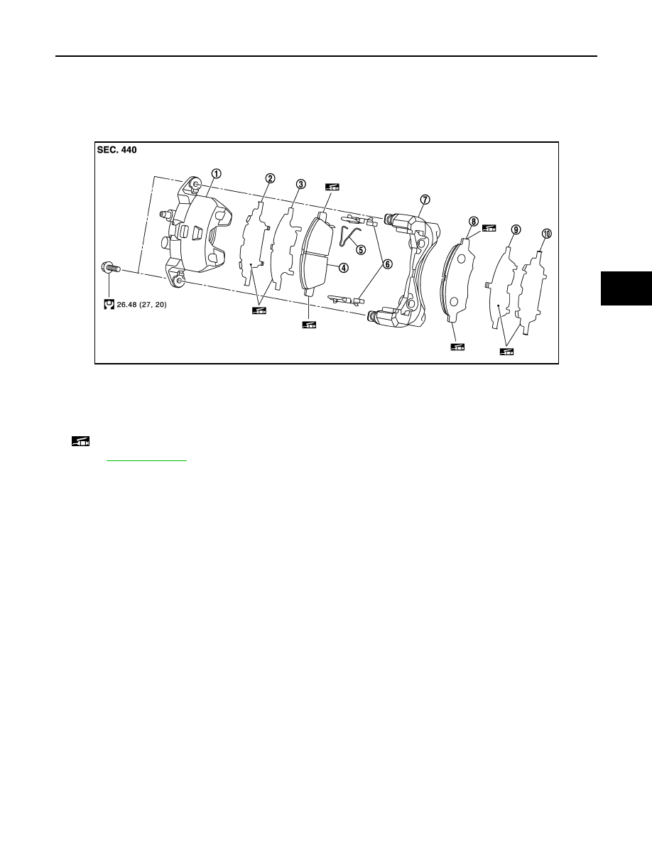
BRAKE PAD : Exploded View

INFOID:0000000005986599

BRAKE PAD : Removal and Installation

INFOID:0000000005986600

REMOVAL

WARNING:

Clean any dust from the brake caliper and brake pads with a vacuum dust collector. Never blow with
compressed air.

CAUTION:

• Never depress the brake pedal while removing the brake pads because the piston may pop out.
• Never spill or splash brake fluid on the disc rotor.
1.

Remove tires.

2.

Remove lower sliding pin bolt.

3.

Suspend the cylinder body with suitable wire so that the brake hose will not stretch. Then remove the pad
return spring, brake pads, shims, shim covers and pad retainers from the torque member.

CAUTION:

• Never deform the pad return spring when removing the pad return spring from the brake pad.
• Never deform the pad retainer when removing the pad retainer from the torque member. 
• Never damage the piston boot.
• Never drop the brake pads, shims, and the shim covers.
• Remember each position of the removed brake pads.

INSTALLATION

WARNING:

Clean any dust from the brake caliper and brake pads with a vacuum dust collector. Never blow with
compressed air.

CAUTION:

1.

Cylinder body

2.

Inner shim cover

3.

Inner shim

4.

Inner pad (with pad wear sensor)

5.

Pad return spring

6.

Pad retainer

7.

Torque member

8.

Outer pad

9.

Outer shim

10.

Outer shim cover

: Apply PBC (Poly Butyl Cuprysil) grease or silicone-based grease.

Refer to 

GI-4, "Components"

 for symbols not described on the above.

JPFIA0763GB

BR-34

< REMOVAL AND INSTALLATION >

FRONT DISC BRAKE

• Never depress the brake pedal while removing the brake pads or the cylinder body because the pis-

ton may pop out.

• Never spill or splash brake fluid on the disc rotor.

1.

Install the pad retainers to the torque member if the pad retainers has been removed.

CAUTION:

• Securely assemble the pad retainers so that it will not be lifted up from the torque member.
• Never deform the pad retainers.

2.

Apply PBC (Poly Butyl Cuprysil) grease or silicone-based
grease to the mating faces between the inner shim (A) and the
inner shim cover (B), and install them to the inner pad. 

CAUTION:

Always replace the shim together with the shim cover when
replacing the brake pad.

3.

Apply PBC (Poly Butyl Cuprysil) grease or silicone-based
grease to the mating faces between the outer shim (A) and the
outer shim cover (B), and install them to the outer pad. 

CAUTION:

Always replace the shim together with the shim cover when
replacing the brake pad.

4.

Apply PBC (Poly Butyl Cuprysil) grease or silicone-based grease to the mating faces between the brake
pads (C) and the pad retainers, and Install the brake pads to the torque member.

5.

Install the pad return spring to the brake pad.

CAUTION:

Never deform the pad return spring.

6.

Install cylinder body to torque member.

CAUTION:

• Never damage the piston boot.
• When replacing brake pad with new one, check a brake fluid level in the reservoir tank because

brake fluid returns to master cylinder reservoir tank when pressing piston in.

NOTE:
Use a disc brake piston tool to easily press piston. 

7.

Install the lower sliding pin bolt and tighten it to the specified torque.

8.

Depress the brake pedal several times to check that no drag feel is present for the front disc brake. Refer
to 

BR-34, "BRAKE PAD : Inspection"

.

9.

Install tires.

BRAKE PAD : Inspection

INFOID:0000000005986601

INSPECTION AFTER REMOVAL

Replace the shims and the shim covers if rust is excessively attached.

INSPECTION AFTER INSTALLATION

1.

Check a drag of front disc brake. If any drag is found, follow the procedure described below.

2.

Remove brake pads. Refer to 

BR-33, "BRAKE PAD : Removal and Installation"

.

3.

Press the pistons. Refer to 

BR-33, "BRAKE PAD : Removal and Installation"

.

4.

Install brake pads. Refer to 

BR-33, "BRAKE PAD : Removal and Installation"

.

5.

Depress the brake pedal several times.

6.

Check a drag of front disc brake again. If any drag is found, disassemble the cylinder body. Refer to 

BR-

36, "BRAKE CALIPER ASSEMBLY : Disassembly and Assembly"

7.

Burnish contact surfaces brake pads and disc rotor after refinishing or replacing brake pads, or if a soft
pedal occurs at very low mileage. Refer to 

BR-13, "BRAKE PAD : Inspection and Adjustment"

.

BRAKE CALIPER ASSEMBLY

BRAKE CALIPER ASSEMBLY : Exploded View

INFOID:0000000005986602

REMOVAL

JPFIA0764ZZ

FRONT DISC BRAKE

BR-35

< REMOVAL AND INSTALLATION >

C

D

E

G

H

I

J

K

L

M

A

B

BR

N

O

P

DISASSEMBLY

BRAKE CALIPER ASSEMBLY : Removal and Installation

INFOID:0000000005986603

REMOVAL

WARNING:

Clean any dust from the brake caliper and brake pads with a vacuum dust collector. Never blow with
compressed air.

1.

Brake caliper assembly

Refer to 

GI-4, "Components"

 for symbols in the figure.

JPFIA0510GB

1.

Cap

2.

Bleeder valve

3.

Cylinder body

4.

Piston seal

5.

Piston

6.

Piston boot

7.

Sliding pin

8.

Sliding pin boot

9.

Bushing

10.

Torque member

: Apply rubber grease.

: Apply brake fluid.

Refer to 

GI-4, "Components"

 for symbols not described on the above.

JPFIA0511GB

BR-36

< REMOVAL AND INSTALLATION >

FRONT DISC BRAKE

CAUTION:

Never spill or splash brake fluid on painted surfaces. Brake fluid may seriously damage paint. Wipe it
out immediately and wash with water if it gets on a protect surface.

1.

Remove tires.

2.

Fix the disc rotor using wheel nuts.

3.

Drain brake fluid. Refer to 

BR-9, "Draining"

.

CAUTION:

Never spill or splash brake fluid on the disc rotor.

4.

Remove union bolt and copper washer, and disconnect brake hose from caliper assembly. Refer to 

BR-

19, "FRONT : Removal and Installation"

.

CAUTION:

Never depress the brake pedal. Brake fluid may splash while removing the brake hose.

5.

Remove torque member mounting bolts, and remove brake caliper assembly.

CAUTION:

Never drop brake pad and caliper assembly.

6.

Remove disc rotor. Refer to 

FAX-9, "Removal and Installation"

.

INSTALLATION

WARNING:

Clean any dust from the brake caliper and brake pads with a vacuum dust collector. Never blow with
compressed air.

CAUTION:

• Never depress the brake pedal. Brake fluid may splash while removing the brake hose.
• Never spill or splash brake fluid on painted surfaces. Brake fluid may seriously damage paint. Wipe it

out immediately and wash with water if it gets on a protect surface.

• Never allow foreign matter (e.g. dust) and oils other than brake fluid to enter the reservoir tank.

1.

Install disc rotor. Refer to 

FAX-9, "Removal and Installation"

.

2.

Install the brake caliper assembly to the steering knuckle and tighten the torque member mounting bolts to
the specified torque.

CAUTION:

Never spill or splash any grease and moisture on the brake caliper assembly mounting face,
threads, mounting bolts and washers. Wipe out any grease and moisture.

3.

Install brake hose and copper washers to brake caliper assembly, and tighten union bolts to the specified
torque. Refer to 

BR-19, "FRONT : Removal and Installation"

.

CAUTION:

Never reuse copper washer.

4.

Refill with new brake fluid and perform the air bleeding. Refer to 

BR-10, "Bleeding Brake System"

.

CAUTION:

• Never reuse drained brake fluid.
• Never spill or splash brake fluid on the disc rotor.

5.

Check a drag of front disc brake. If any drag is found, refer to 

BR-38, "BRAKE CALIPER ASSEMBLY :

Inspection"

.

6.

Install tires.

BRAKE CALIPER ASSEMBLY : Disassembly and Assembly

INFOID:0000000005986604

DISASSEMBLY

NOTE:
Never remove the torque member, brake pad and pad retainers when disassembling and assembling the cyl-
inder body.

1.

Remove the sliding pin bolt, and remove the cylinder body from the torque member. Refer to 

BR-33,

"BRAKE PAD : Removal and Installation"

.

CAUTION:

Fix the brake pad at suitable tape so that the brake pad will not drop.

2.

Remove sliding pins and sliding pin boots from torque member.

3.

Remove bushing from sliding pin.


Content   ..  38  39  40  41   ..