Nissan March K13. Manual - part 38
BRAKE MASTER CYLINDER
BR-25
< REMOVAL AND INSTALLATION >
C
D
E
G
H
I
J
K
L
M
A
B
BR
N
O
P
BRAKE MASTER CYLINDER
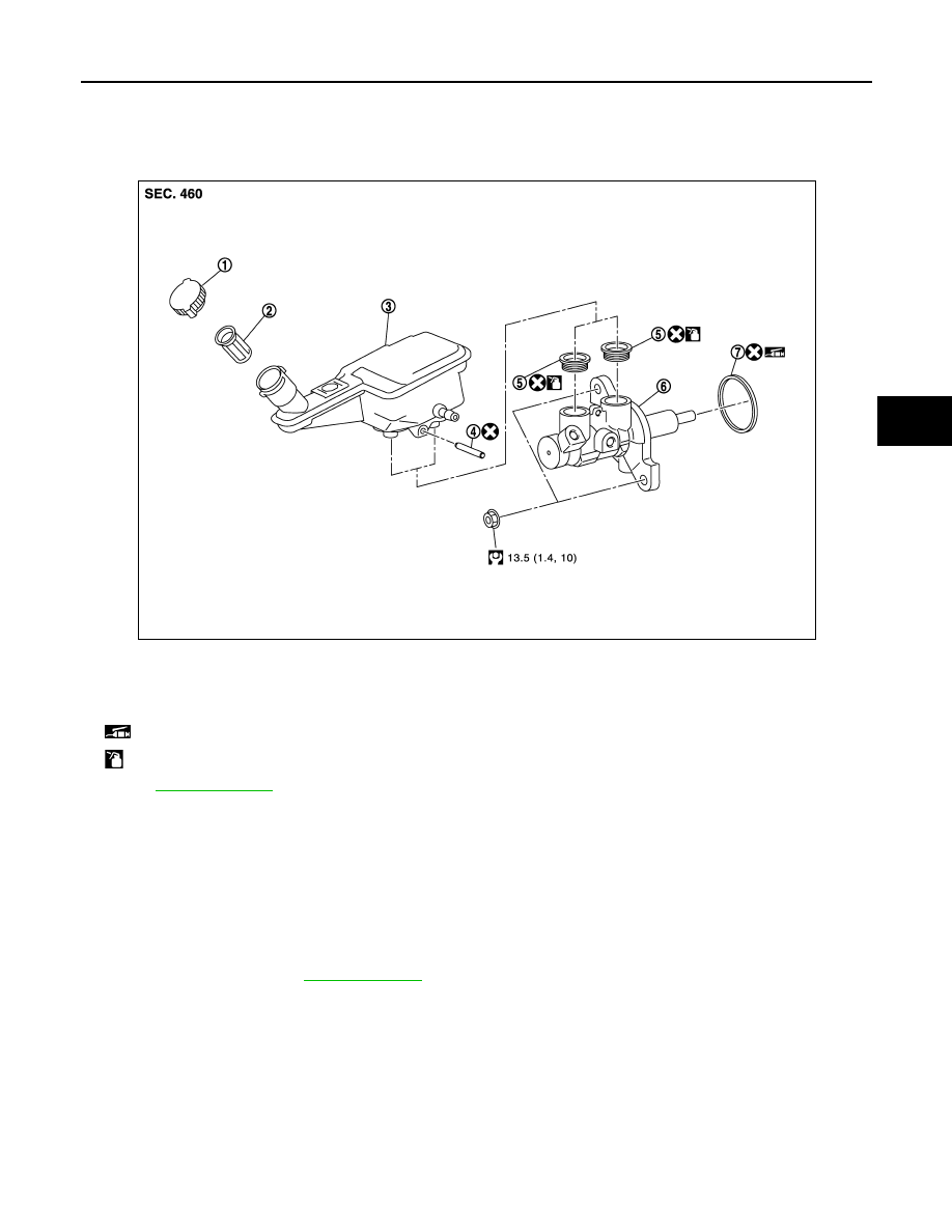
Exploded View
INFOID:0000000005986589
Removal and Installation
INFOID:0000000005986590
REMOVAL
CAUTION:
• Never spill or splash brake fluid on painted surfaces. Brake fluid may seriously damage paint. Wipe it
off immediately and wash with water if it gets on a painted surface.
• Depress the brake pedal several times to release the vacuum pressure from the brake booster. Then
remove the master cylinder assembly.
1.
Drain brake fluid. Refer to
.
2.
Disconnect the brake fluid level switch harness connector.
3.
Remove the brake tube from between dual proportioning valve and master cylinder assembly with a flare
nut wrench.
CAUTION:
Never scratch the flare nut and the brake tube.
4.
Remove the master cylinder assembly.
CAUTION:
• Never deform or bend the brake tubes.
• Never depress the brake pedal after the master cylinder assembly is removed.
1.
Reservoir cap
2.
Oil strainer
3.
Reservoir tank
4.
Pin
5.
Grommet
6.
Cylinder body
7.
O-ring
: Apply PBC (Poly Butyl Cuprysil) grease or silicone-based grease.
: Apply brake fluid.
Refer to
for symbols not described on the above.
JPFIA0760GB