Nissan March K13. Manual - part 41
FRONT DISC BRAKE
BR-37
< REMOVAL AND INSTALLATION >
C
D
E
G
H
I
J
K
L
M
A
B
BR
N
O
P
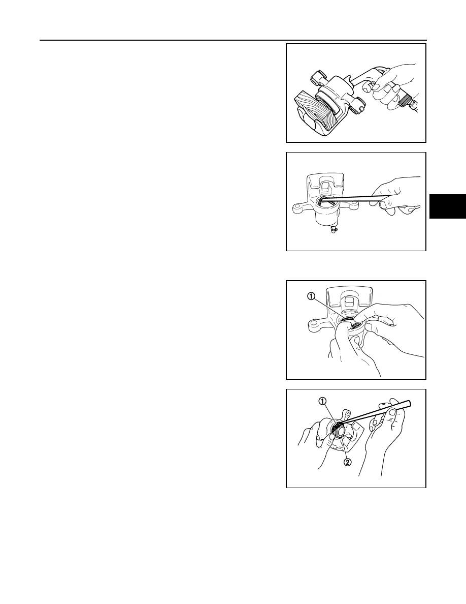
4.
Place a wooden block as shown in the figure, and blow air from
union bolt mounting hole to remove pistons and piston boots.
CAUTION:
Never get fingers caught in the pistons.
5.
Remove piston seal from cylinder body using suitable tool.
CAUTION:
Be careful not to damage a cylinder inner wall.
6.
Remove bleeder valve and cap.
ASSEMBLY
1.
Install bleeder valve and cap.
2.
Apply rubber grease to piston seals (1), and install them to cylin-
der body.
CAUTION:
Never reuse piston seals.
3.
Apply rubber grease to piston boots (1). Cover the piston (2) end
with piston boot, and then install cylinder side lip on piston boot
securely into a groove on cylinder body.
CAUTION:
Never reuse piston boots.
MAA0272D
JPFIA0738ZZ
JPFIA0039ZZ
JPFIA0739ZZ