Almera Tino V10 (2003 year). Manual - part 235
SRS697
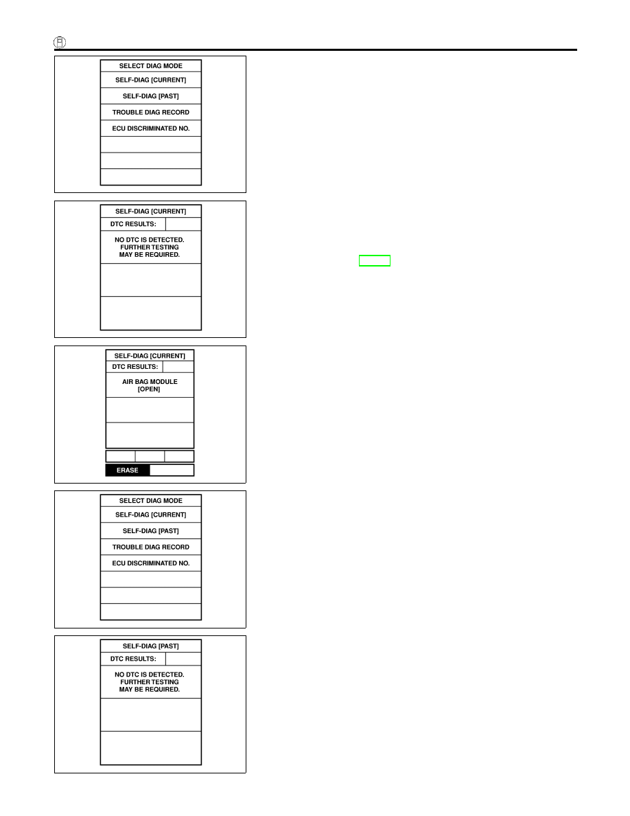
6.
Touch “SELF-DIAG [CURRENT]”.
SRS701
7.
If no malfunction is detected on “SELF-DIAG [CURRENT]”,
repair of SRS is completed. Go to step 8.
If any malfunction is displayed on “SELF-DIAG [CURRENT]”,
the malfunctioning part is not repaired completely or another
malfunctioning part is detected. Go to DIAGNOSTIC PROCE-
DURE 2, page RS-44, and repair malfunctioning part com-
pletely.
SRS773
8.
Touch “ERASE”.
NOTE:
Touch “ERASE” to clear the memory of the malfunction
(“SELF-DIAG [PAST]”).
If the memory of the malfunction in “SELF-DIAG [PAST]” is not
erased, the User mode shows the system malfunction by the
operation of the warning lamp even if the malfunction is repaired
completely.
SRS697
9.
Touch “BACK” key of CONSULT-II to “SELECT SYSTEM”
screen. Touch “SELF-DIAG [PAST]”.
SRS702
10. Check that no malfunction is detected on “SELF-DIAG
[PAST]”.
SUPPLEMENTAL RESTRAINT SYSTEM (SRS)
Trouble Diagnoses with CONSULT-II (Cont’d)
RS-48