Almera Tino V10 (2003 year). Manual - part 234
SRS145-F
2.
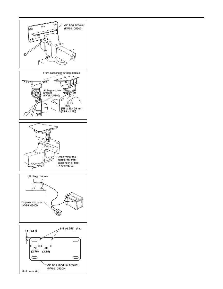
Firmly secure air bag module bracket (SST: KV99105300) in a
vise.
NRS113
3.
Match the two holes in air bag module bracket (held in vise)
and front passenger air bag module and fix them with two bolts
[M8
×
25 - 30 mm (0.98 - 1.18 in)].
CAUTION:
If a gap exists between front passenger air bag module and air
bag module bracket, use a piece of wood inserted in the gap
to stabilize the front passenger air bag module.
NRS114
4.
Connect deployment tool adapter (SST: KV99108300) to
deployment tool (SST: KV99106400) connector and front pas-
senger air bag module connector.
5.
Connect red clip of deployment tool to battery positive termi-
nal and black clip to negative terminal.
6.
The lamp on the right side of the tool, marked “deployment tool
power”, should glow green, not red.
7.
Press the button on the deployment tool. The left side lamp on
the tool, marked “air bag connector voltage”, will illuminate and
the front passenger air bag module will deploy.
SRS020-A
CAUTION:
I
When deploying the front passenger air bag module, do
not stand on the deploying side.
I
Stand at least 5 m (16 ft) away from the front passenger
air bag module.
SRS490-C
Deployment of Front Side Air Bag Module (Built-in
type) (Outside of vehicle)
NLRS0022S0204
1.
Make 6.5 mm (0.256 in) diameter holes in air bag module
bracket (SST: KV99105300) at the position shown in figure at
left.
2.
Firmly secure air bag module bracket (SST: KV99105300) in a
vise.
SUPPLEMENTAL RESTRAINT SYSTEM (SRS)
Disposal of Air Bag Module and Seat Belt Pre-tensioner (Cont’d)
RS-32