Almera Tino V10 (2003 year). Manual - part 219
SLC283B
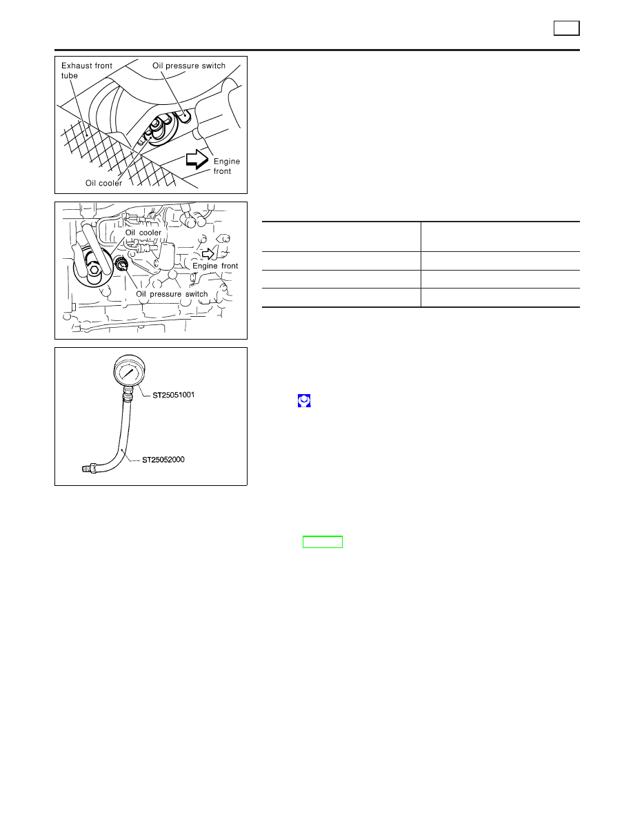
Oil Pressure Check
NLLC0042
JLC284B
SLC926-A
WARNING:
I
Be careful not to burn yourself, as the engine and oil may
be hot.
I
Oil pressure check should be done in “Neutral position”.
1.
Check oil level.
2.
Remove exhaust front tube.
3.
Remove oil pressure switch.
4.
Install pressure gauge.
5.
Install exhaust front tube.
6.
Start engine and warm it up to normal operating temperature.
7.
Check oil pressure with engine running under no-load.
Engine speed
rpm
Approximate discharge pressure
kPa (bar, kg/cm
2
, psi)
Idle speed
More than 140 (1.40, 1.43, 20.3)
2,000
More than 270 (2.69, 2.75, 39.1)
4,000
More than 430 (4.29, 4.38, 62.3)
If difference is extreme, check oil passage and oil pump
for oil leaks.
8.
After the inspections, install the oil pressure switch as follows.
a.
Remove the old sealant adhering to the switch and engine.
b.
Apply Genuine Liquid Gasket or equivalent to the thread and
tighten.
: 13 - 17 N·m (1.25 - 1.75 kg-m, 9 - 12 ft-lb)
Oil Pump
REMOVAL AND INSTALLATION
NLLC0043
I
When installing oil pump, apply engine oil to rotors.
Refer to EM-176, “Primary Timing Chain” for removal.
Reinstall all parts in the reverse order of removal.
ENGINE LUBRICATION SYSTEM
YD
Oil Pressure Check
LC-24