Almera Tino V10 (2003 year). Manual - part 218
SLC101B
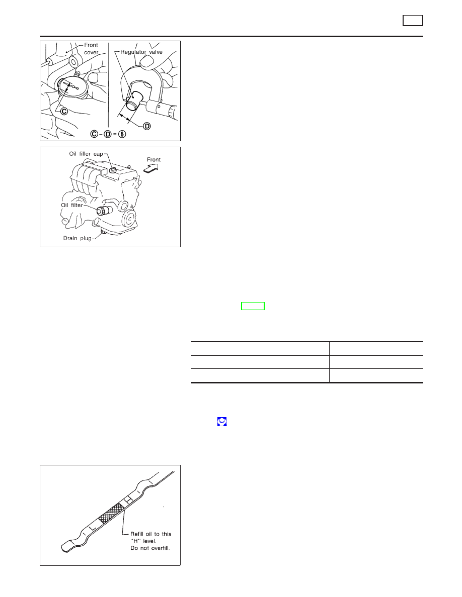
4.
Check regulator valve to front cover clearance.
Clearance 6:
0.052 - 0.088 mm (0.0020 - 0.0035 in)
If it exceeds the limit, replace front cover assembly.
SMA915C
Changing Engine Oil
NLLC0035
WARNING:
‰
Be careful not to burn yourself, as the engine oil is hot.
‰
Prolonged and repeated contact with used engine oil may
cause skin cancer; try to avoid direct skin contact with
used oil. If skin contact is made, wash thoroughly with
soap or hand cleaner as soon as possible.
1.
Warm up engine, and check for oil leakage from engine com-
ponents.
2.
Stop engine and wait more than 10 minutes.
3.
Remove drain plug and oil filler cap.
4.
Drain oil and refill with new engine oil.
Oil specification and viscosity (For Europe):
‰
API grade SG, SH or SJ
‰
ACEA grade A1-98, A3-98
‰
ILSAC grade GF-I, GF-II
Refer to MA-20, “RECOMMENDED FLUIDS AND LUBRI-
CANTS”.
Refill oil capacity (Approximate):
Unit:
(Imp qt)
With oil filter chang
e 2.7 (2-3/8
)
Without oil filter chang
e 2.5 (2-1/4
)
Dry engine (engine overhaul
) 3.1 (2-3/4
)
CAUTION:
‰
Be sure to clean drain plug and install with new washer.
Drain plug:
: 29 - 39 N·m (3.0 - 4.0 kg-m, 22 - 29 ft-lb)
‰
The refill capacity changes depending on the oil tempera-
ture and drain time, use these values as a reference and
be certain to check with the dipstick when changing the
oil.
SMA390C
5.
Check oil level.
6.
Start engine and check area around drain plug and oil filter for
oil leakage.
7.
Run engine for a few minutes, then turn it off. After several
minutes, check oil level.
ENGINE LUBRICATION SYSTEM
QG
Oil Pump (Cont’d)
LC-8