Almera Tino V10 (2003 year). Manual - part 191
CIRCUIT CHECK BETWEEN ABS ACTUATOR AND ELECTRIC UNIT (CONTROL UNIT) AND
SMART ENTRANCE CONTROL UNIT
=NLEL0656S06
1
CHECK CONNECTOR
1. Turn ignition switch OFF.
2. Disconnect the negative battery cable.
3. Check following terminals and connector for damage, bend and loose connection (connector side and harness side).
LHD models
I
Harness connector E125
I
Harness connector M82
RHD models
I
Harness connector E145
I
Harness connector M80
OK or NG
OK
©
GO TO 2.
NG
©
Repair terminal or connector.
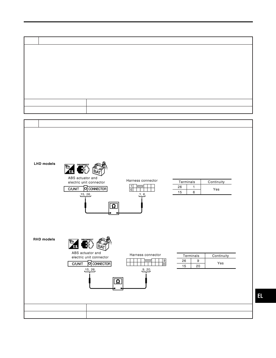
2
CHECK HARNESS FOR OPEN CIRCUIT
1. Disconnect ABS actuator and electric unit (control unit) connector and harness connector E125 (LHD models) or har-
ness connector E145 (RHD models).
2. Check the following.
LHD models
I
Continuity between ABS actuator and electric unit (control unit) harness connector E142 terminals 26 (L), 15 (R) and
harness connector E125 terminals 1 (L), 6 (R)
YEL450E
RHD models
I
Continuity between ABS actuator and electric unit (control unit) harness connector E142 terminals 26 (L), 15 (R) and
harness connector E145 terminals 9 (L), 20 (R)
YEL451E
OK or NG
OK
©
GO TO 3.
NG
©
Repair harness.
GI
MA
EM
LC
EC
FE
CL
MT
AT
AX
SU
BR
ST
RS
BT
HA
SC
IDX
CAN SYSTEM (TYPE 4)
Trouble Diagnoses (Cont’d)
EL-545