Almera Tino V10 (2003 year). Manual - part 189
SEL723Y
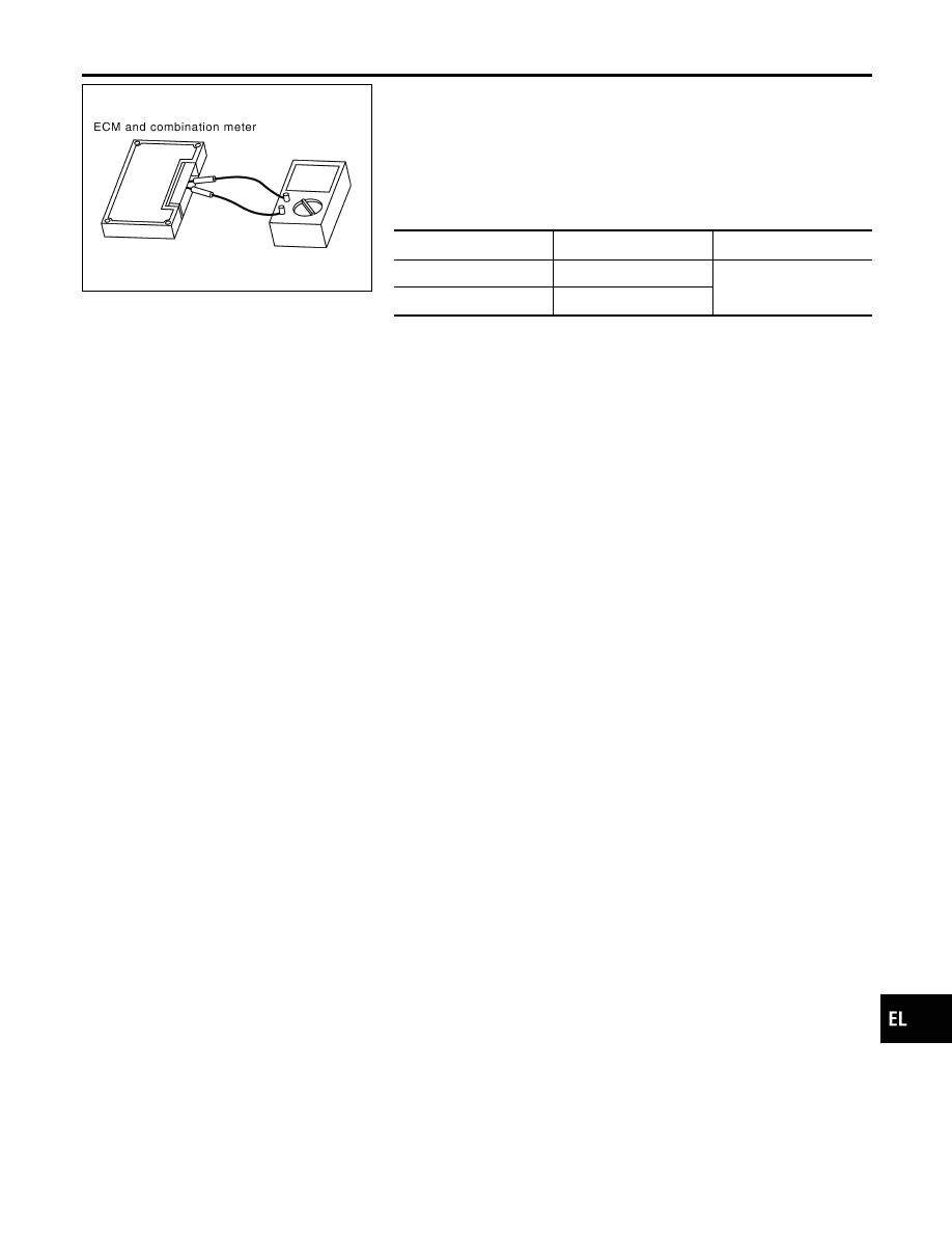
Component Inspection
=NLEL0647
ECM/COMBINATION METER INTERNAL CIRCUIT
INSPECTION
NLEL0647S01
I
Remove ECM and combination meter from vehicle.
I
Check resistance between ECM terminals 94 and 86.
I
Check resistance between combination meter terminals 39
and 40.
Unit
Terminal
Resistance value (
Ω
)
ECM
94 - 86
Approx. 108 - 132
Combination meter
39 - 40
GI
MA
EM
LC
EC
FE
CL
MT
AT
AX
SU
BR
ST
RS
BT
HA
SC
IDX
CAN SYSTEM (TYPE 2)
Component Inspection
EL-513