Almera Tino V10 (2003 year). Manual - part 187
ECM CIRCUIT CHECK
=NLEL0641S08
1
CHECK CONNECTOR
1. Turn ignition switch OFF.
2. Disconnect the negative battery cable.
3. Check the terminals and connector of ECM for damage, bend and loose connection (control module side and harness
side).
OK or NG
OK
©
GO TO 2.
NG
©
Repair terminal or connector.
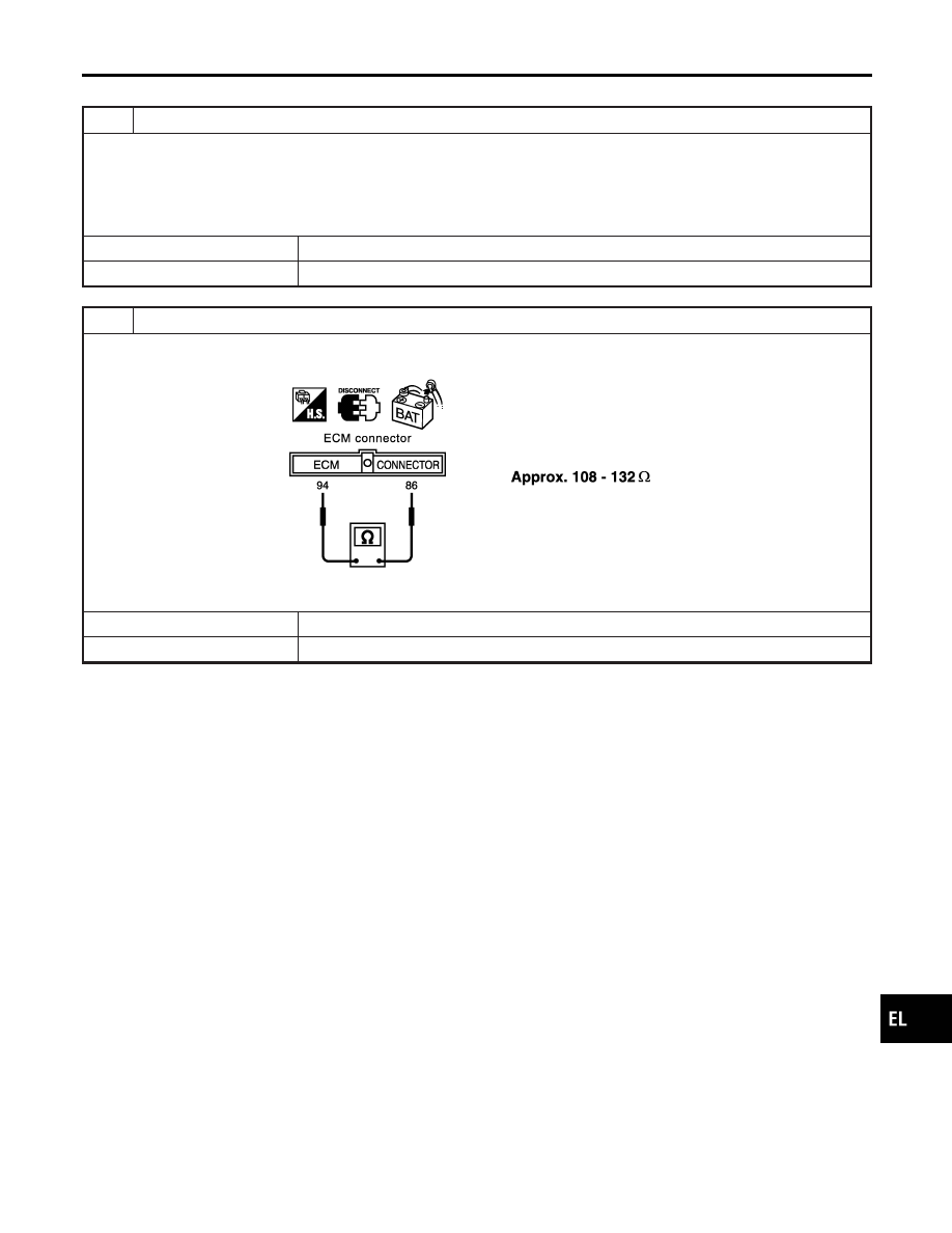
2
CHECK HARNESS FOR OPEN CIRCUIT
1. Disconnect ECM connector.
2. Check resistance between ECM harness connector M107 terminals 94 (L) and 86 (R).
SEL812Y
OK or NG
OK
©
Replace ECM.
NG
©
Repair harness between ECM and TCM.
GI
MA
EM
LC
EC
FE
CL
MT
AT
AX
SU
BR
ST
RS
BT
HA
SC
IDX
CAN SYSTEM (TYPE 1)
Trouble Diagnoses (Cont’d)
EL-481