Almera Tino V10 (2003 year). Manual - part 182
Terminal No. (wire
color)
Item
Signal
input/
output
Condition
Voltage
Example of symp-
tom
+
−
Ignition
switch
Operation
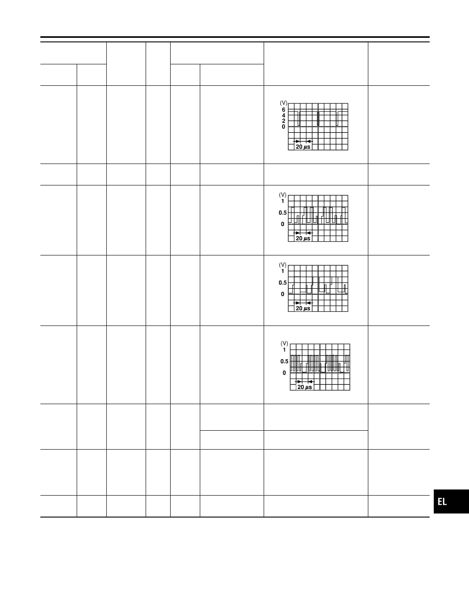
15 (G)
17
RGB syn-
chronizing
signal
Output
ON
Press the “MAP”
switch.
SKIA0164E
RGB screen is
rolling.
17 (B)
ground
RGB
Ground
—
ON
—
Approx. 0V
—
18 (Y)
17
RGB signal
(R: red)
Output
ON
Select “SCREEN
ADJUSTMENT” of
CONFIRMATION/
ADJUSTMENT
function.
SKIA0165E
RGB screen looks
bluish.
21 (W)
17
RGB signal
(G: green)
Output
ON
Select “SCREEN
ADJUSTMENT” of
CONFIRMATION/
ADJUSTMENT
function.
SKIA0166E
RGB screen looks
reddish.
24 (L)
17
RGB signal
(B: blue)
Output
ON
Select “SCREEN
ADJUSTMENT” of
CONFIRMATION/
ADJUSTMENT
function.
SKIA0167E
RGB screen looks
yellowish.
25
LHD:
(R/G)
RHD:
(Y/R)
ground
Illumination
control sig-
nal
Input
ON
Lighting switch ON
(position 1)
Battery voltage
Screen does not
switch between
daytime mode and
nighttime mode.
Lighting switch OFF
Approx. 0
27 (Y/G)
ground
Ignition sig-
nal
Input
ON
—
Battery voltage
A/C operation is
not possible.
Vehicle informa-
tion setting is not
possible.
31 (B)
—
Shield
ground
—
—
—
—
—
GI
MA
EM
LC
EC
FE
CL
MT
AT
AX
SU
BR
ST
RS
BT
HA
SC
IDX
NAVIGATION SYSTEM
Terminals and Reference Value for AV and NAVI Control Unit (Cont’d)
EL-401