Almera Tino V10 (2003 year). Manual - part 181


  Index      Manuals     Almera Tino V10 (2003 year) - Service and Repair Manual


Search            copyright infringement  


Content      ..     179      180      181      182     ..


Almera Tino V10 (2003 year). Manual - part 181


SKIA1400E

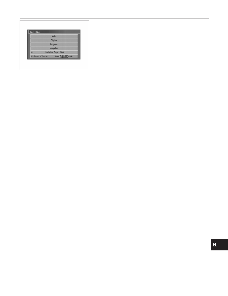
GUIDE VOLUME SETTING

NLEL0593S21

Description

NLEL0593S2101

Following voice guidance setting can be changed.

Activation/Deactivation Setting

NLEL0593S2102

I

The voice prompt can be turned on/off by pressing the “Guid-
ance Volume” button.

Voice Volume Setting

NLEL0593S2103

I

Volume of the voice can be controlled by bending the joystick
to left/right.

NATS NAVI LINK

NLEL0593S22

Description

NLEL0593S2201

The link with the NATS IMMU implies that the AV and NAVI control
unit can basically only be operated if connected to the matching
NATS IMMU to which the AV and NAVI control unit was initially fit-
ted on the production line.
The Navigation system does not operate because it is judged that
the code collation with NATS IMMU is illegal when the control unit
of other cars is installed.

Precautions for AV and NAVI Control Unit
Replacement

NLEL0594

I

When replacing the AV and NAVI control unit, eject the map
DVD-ROM before disconnecting the battery.

I

The AV and NAVI control unit has the following information
stored in its memory. Record the memory contents before
replacing the control unit, and input them in the new unit as
necessary.

<RADIO>

I

Preset frequency

I

Area for indicating station, selection of overlapped sta-
tions

<CD>

I

Program status

<Sound quality>

I

Volume balance memory set values

I

Equalizer memory set values

<Image quality>

I

Brightness of light when ON/OFF

I

Dimming switching

I

Display color switching

GI

MA

EM

LC

EC

FE

CL

MT

AT

AX

SU

BR

ST

RS

BT

HA

SC

IDX

NAVIGATION SYSTEM

System Description (Cont’d)

EL-385

<Navigation mode>

I

Latest status (map screen/bird view

T

, reduced scale, rota-

tion angle of map screen, route guide ON/OFF, track
ON/OFF, etc.)

I

Current position

I

Destination, passing point 1 - 5

I

Registered places, their names, etc.

NOTE:
Only removing the battery does not erase the memory.

Component Parts Location

NLEL0595

For details, refer to “ELECTRICAL UNIT LOCATION” (EL-596) and
“HARNESS LAYOUT” (EL-600).

Location of Antenna

NLEL0596

Refer to EL-212, “Location of Antenna”.

NAVIGATION SYSTEM

Precautions for AV and NAVI Control Unit Replacement (Cont’d)

EL-386

Schematic

NLEL0597

YEL021E

GI

MA

EM

LC

EC

FE

CL

MT

AT

AX

SU

BR

ST

RS

BT

HA

SC

IDX

NAVIGATION SYSTEM

Schematic

EL-387

Wiring Diagram — NAVI —

NLEL0598

LHD MODELS

NLEL0598S01

YEL022E

NAVIGATION SYSTEM

Wiring Diagram — NAVI —

EL-388

YEL023E

GI

MA

EM

LC

EC

FE

CL

MT

AT

AX

SU

BR

ST

RS

BT

HA

SC

IDX

NAVIGATION SYSTEM

Wiring Diagram — NAVI — (Cont’d)

EL-389

YEL024E

NAVIGATION SYSTEM

Wiring Diagram — NAVI — (Cont’d)

EL-390

YEL025E

GI

MA

EM

LC

EC

FE

CL

MT

AT

AX

SU

BR

ST

RS

BT

HA

SC

IDX

NAVIGATION SYSTEM

Wiring Diagram — NAVI — (Cont’d)

EL-391

YEL026E

NAVIGATION SYSTEM

Wiring Diagram — NAVI — (Cont’d)

EL-392

YEL027E

GI

MA

EM

LC

EC

FE

CL

MT

AT

AX

SU

BR

ST

RS

BT

HA

SC

IDX

NAVIGATION SYSTEM

Wiring Diagram — NAVI — (Cont’d)

EL-393

RHD MODELS

NLEL0598S02

YEL028E

NAVIGATION SYSTEM

Wiring Diagram — NAVI — (Cont’d)

EL-394

YEL029E

GI

MA

EM

LC

EC

FE

CL

MT

AT

AX

SU

BR

ST

RS

BT

HA

SC

IDX

NAVIGATION SYSTEM

Wiring Diagram — NAVI — (Cont’d)

EL-395

YEL030E

NAVIGATION SYSTEM

Wiring Diagram — NAVI — (Cont’d)

EL-396

YEL031E

GI

MA

EM

LC

EC

FE

CL

MT

AT

AX

SU

BR

ST

RS

BT

HA

SC

IDX

NAVIGATION SYSTEM

Wiring Diagram — NAVI — (Cont’d)

EL-397

YEL032E

NAVIGATION SYSTEM

Wiring Diagram — NAVI — (Cont’d)

EL-398

YEL033E

GI

MA

EM

LC

EC

FE

CL

MT

AT

AX

SU

BR

ST

RS

BT

HA

SC

IDX

NAVIGATION SYSTEM

Wiring Diagram — NAVI — (Cont’d)

EL-399

Terminals and Reference Value for AV and
NAVI Control Unit

NLEL0600

I

For measurements made with IGN switch ON, if possible, measure with engine running to prevent battery
discharge.

I

Use a circuit tester and oscilloscope or CONSULT-ll for measurement.

Terminal No. (wire

color)

Item

Signal

input/

output

Condition

Voltage

Example of symp-

tom

+

Ignition

switch

Operation

1 (B)

ground

Ground

ON

Approx. 0V

2 (Y)

ground

Battery

power

Input

OFF

Battery voltage

System does not

work properly.

3 (Y)

4 (B)

ground

Ground

ON

Approx. 0V

5 (BR)

ground

Illumination

ground

ON

Approx. 0V

6 (P)

ground

ACC signal

Input

ACC

Battery voltage

System does not

work properly.

7 (BR)

8 (Y)

voice guide

signal

Output

ON

Press the “voice”

switch.

SKIA0171J

Only route guide

and operation

guide are not

heard.

9(B)

Shield

ground

11 (B)

17

Vertical

synchroniz-

ing signal

Input

ON

SKIA0161E

Superimposed

screen is rolling.

12 (R)

17

RGB area

signal

Output

ON

Press the “info”s-

witch.

SKIA0162E

RGB screen is not

shown.

13 (BR)

17

Horizontal

synchroniz-

ing signal

Input

ON

Select“ Display” in

“Setting” mode and

display the rear-

view picture on the

screen.

SKIA0163E

Superimposed

screen is not

shown.

NAVIGATION SYSTEM

Terminals and Reference Value for AV and NAVI Control Unit

EL-400


Content      ..     179      180      181      182     ..