Almera Tino V10 (2003 year). Manual - part 176


  Index      Manuals     Almera Tino V10 (2003 year) - Service and Repair Manual


Search            copyright infringement  


Content      ..     174      175      176      177     ..


Almera Tino V10 (2003 year). Manual - part 176


2

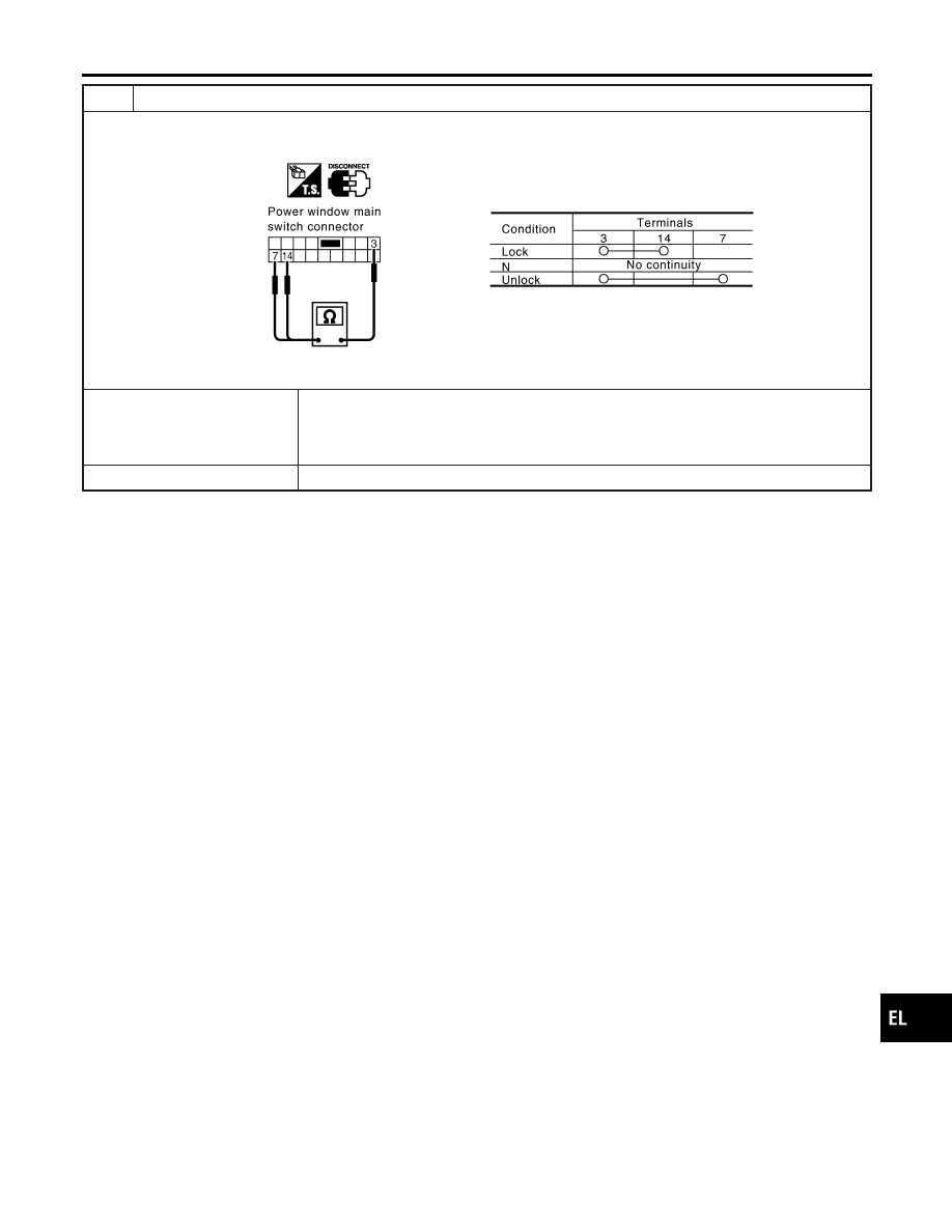
CHECK DOOR LOCK/UNLOCK SWITCH

1. Disconnect power window main switch connector.
2. Check continuity between power window main switch terminals.

YEL349E

OK or NG

OK

©

Check the following.

I

Ground circuit for power window main switch

I

Harness for open or short between power window main switch and smart entrance
control unit connector

NG

©

Replace power window main switch (door lock/unlock switch).

GI

MA

EM

LC

EC

FE

CL

MT

AT

AX

SU

BR

ST

RS

BT

HA

SC

IDX

POWER DOOR LOCK — SUPER LOCK —

Trouble Diagnosis (Cont’d)

EL-305

DOOR LOCK ACTUATOR CHECK

=NLEL0573S08

Driver Side

NLEL0573S0801

1

CHECK DOOR LOCK SIGNAL

1. Disconnect door lock actuator (driver side) harness connector.
2. Check voltage between door lock actuator harness connector D10 terminal 3 (L), 6 (W/R) and ground.

YEL354E

MTBL1695

OK or NG

OK

©

Replace door lock actuator assembly driver side.

NG

©

GO TO 2.

2

CHECK DOOR LOCK ACTUATOR CIRCUIT

1. Disconnect smart entrance control unit harness connector.
2. Check continuity between door lock actuator (driver side) harness connector D10 terminal 3 (L), 6 (W/R) and smart

entrance control unit harness connector M101 terminal 51 (L/R), 52 (Y).

YEL355E

MTBL1696

OK or NG

OK

©

Replace smart entrance control unit.

NG

©

Check harness for open or short between smart entrance control unit and door lock
actuator assembly driver side.

POWER DOOR LOCK — SUPER LOCK —

Trouble Diagnosis (Cont’d)

EL-306

Passenger Side

=NLEL0573S0802

1

CHECK DOOR LOCK SIGNAL

1. Disconnect door lock actuator (passenger side) harness connector.
2. Check voltage between door lock actuator harness connector D39 terminal 1 (W/R), 4 (G/R) and ground.

YEL356E

MTBL1697

OK or NG

OK

©

Replace door lock actuator assembly passenger side.

NG

©

GO TO 2.

2

CHECK DOOR LOCK ACTUATOR CIRCUIT

1. Disconnect smart entrance control unit connector.
2. Check continuity between door lock actuator assembly passenger side harness connector D39 terminal 1 (W/R), 4

(G/R) and smart entrance control unit harness connector M101 terminal 52 (Y), 54 (G/Y).

YEL357E

MTBL1698

OK or NG

OK

©

Replace smart entrance control unit.

NG

©

Check harness for open or short between smart entrance control unit and door lock
actuator assembly passenger side.

GI

MA

EM

LC

EC

FE

CL

MT

AT

AX

SU

BR

ST

RS

BT

HA

SC

IDX

POWER DOOR LOCK — SUPER LOCK —

Trouble Diagnosis (Cont’d)

EL-307

Rear LH Side

NLEL0573S0803

1

CHECK DOOR LOCK SIGNAL

1. Disconnect door lock actuator assembly rear LH harness connector.
2. Check voltage between door lock actuator assembly rear LH harness connector D55 terminal 1 (W/R), 4 (G/R) and

ground.

YEL358E

MTBL1699

OK or NG

OK

©

Replace door lock actuator assembly rear LH.

NG

©

GO TO 2.

2

CHECK DOOR LOCK ACTUATOR CIRCUIT

1. Disconnect smart entrance control unit harness connector.
2. Check continuity between door lock actuator assembly rear LH harness connector D55 terminal 1 (W/R), 4 (G/R) and

smart entrance control unit harness connector M101 terminal 52 (Y), 54 (G/Y).

YEL359E

MTBL1700

OK or NG

OK

©

Replace smart entrance control unit.

NG

©

Check harness for open or short between smart entrance control unit and door lock
actuator assembly rear LH.

POWER DOOR LOCK — SUPER LOCK —

Trouble Diagnosis (Cont’d)

EL-308

Rear RH Side

NLEL0573S0804

1

CHECK DOOR LOCK SIGNAL

1. Disconnect door lock actuator assembly rear RH harness connector.
2. Check voltage between door lock actuator assembly rear RH harness connector D65 terminal 3 (R/B), 6 (W/R) and

ground.

YEL360E

MTBL1701

OK or NG

OK

©

Replace door lock actuator assembly rear RH.

NG

©

GO TO 2.

2

CHECK DOOR LOCK ACTUATOR CIRCUIT

1. Disconnect smart entrance control unit harness connector.
2. Check continuity between door lock actuator rear RH harness connector D65 terminal 3 (R/B), 6 (W/R) and smart

entrance control unit harness connector M101 terminal 52 (Y), 54 (G/Y).

YEL361E

MTBL1702

OK or NG

OK

©

Replace smart entrance control unit.

NG

©

Check harness for open or short between smart entrance control unit and door lock
actuator rear RH.

GI

MA

EM

LC

EC

FE

CL

MT

AT

AX

SU

BR

ST

RS

BT

HA

SC

IDX

POWER DOOR LOCK — SUPER LOCK —

Trouble Diagnosis (Cont’d)

EL-309

DOOR SWITCH CHECK

NLEL0573S09

Driver Side

NLEL0573S0901

1

CHECK DOOR SWITCH INPUT SIGNAL

With CONSULT-II

I

Check door switch “DR DOOR SW” in “DATA MONITOR” mode with CONSULT-II.

SIIA1590E

MTBL1703

Without CONSULT-II

1. Turn ignition switch OFF.
2. Check voltage between smart entrance control unit harness connector M100 terminal 43 (R/W) and ground.

SIIA1588E

MTBL1704

OK or NG

OK

©

Door switch driver side is OK.

NG

©

GO TO 2.

POWER DOOR LOCK — SUPER LOCK —

Trouble Diagnosis (Cont’d)

EL-310

2

CHECK DOOR SWITCH

Check continuity between door switch driver side connector B28 terminals 2 and 3.

NEL648

OK or NG

OK

©

Check the following.

I

Door switch driver side ground condition

I

Harness for open or short between smart entrance control unit and door switch driver
side

NG

©

Replace door switch driver side.

GI

MA

EM

LC

EC

FE

CL

MT

AT

AX

SU

BR

ST

RS

BT

HA

SC

IDX

POWER DOOR LOCK — SUPER LOCK —

Trouble Diagnosis (Cont’d)

EL-311

Passenger Side

NLEL0573S0902

1

CHECK DOOR SWITCH INPUT SIGNAL

With CONSULT-II

I

Check door switch “AS DOOR SW” in “DATA MONITOR” mode with CONSULT-II.

SIIA1591E

MTBL1705

Without CONSULT-II

1. Turn ignition switch OFF.
2. Check voltage between smart entrance control unit harness connector M100 terminal 44 (L/OR) and ground.

SIIA1592E

MTBL1706

OK or NG

OK

©

Door switch passenger side is OK.

NG

©

GO TO 2.

POWER DOOR LOCK — SUPER LOCK —

Trouble Diagnosis (Cont’d)

EL-312

2

CHECK DOOR SWITCH

1. Disconnect door switch passenger side connector.
2. Check continuity between door switch passenger side harness connector B22 terminal 1 (R/W) and ground.

SIIA1589E

MTBL1707

OK or NG

OK

©

Check the following.

I

Door switch passenger side ground condition

I

Harness for open or short between smart entrance control unit and door switch pas-
senger side

NG

©

Replace door switch passenger side.

GI

MA

EM

LC

EC

FE

CL

MT

AT

AX

SU

BR

ST

RS

BT

HA

SC

IDX

POWER DOOR LOCK — SUPER LOCK —

Trouble Diagnosis (Cont’d)

EL-313

Rear LH Side

NLEL0573S0903

1

CHECK DOOR SWITCH INPUT SIGNAL

With CONSULT-II

I

Check door switch “RR LH DOOR SW” in “DATA MONITOR” mode with CONSULT-II.

SIIA1593E

MTBL1502

Without CONSULT-II

1. Turn ignition switch OFF.
2. Check voltage between smart entrance control unit harness connector M100 terminal 44 (L/OR) and ground.

SIIA1592E

MTBL1708

OK or NG

OK

©

Door switch is OK.

NG

©

GO TO 2.

POWER DOOR LOCK — SUPER LOCK —

Trouble Diagnosis (Cont’d)

EL-314

2

CHECK DOOR SWITCH

Check continuity between door switch rear LH harness connector B34 terminal 1 (R/W) and ground.

SIIA1595E

MTBL1709

OK or NG

OK

©

Check the following.

I

Door switch rear LH ground condition

I

Harness for open or short between smart entrance control unit and door switch rear
LH

NG

©

Replace door switch rear LH.

GI

MA

EM

LC

EC

FE

CL

MT

AT

AX

SU

BR

ST

RS

BT

HA

SC

IDX

POWER DOOR LOCK — SUPER LOCK —

Trouble Diagnosis (Cont’d)

EL-315

Rear RH Side

NLEL0573S0904

1

CHECK DOOR SWITCH INPUT SIGNAL

With CONSULT-II

I

Check door switch “RR RH DOOR SW” in “DATA MONITOR” mode with CONSULT-II.

SIIA1592E

MTBL1710

Without CONSULT-II

1. Turn ignition switch OFF.
2. Check voltage between smart entrance control unit harness connector M100 terminal 44 (L/OR) and ground.

SIIA1592E

MTBL1711

OK or NG

OK

©

Door switch rear RH is OK.

NG

©

GO TO 2.

POWER DOOR LOCK — SUPER LOCK —

Trouble Diagnosis (Cont’d)

EL-316

2

CHECK DOOR SWITCH

Check continuity between rear door switch RH harness connector B41 terminal 1 (B/W) and ground.

SIIA1595E

MTBL1712

OK or NG

OK

©

Check the following.

I

Door switch rear RH ground condition

I

Harness for open or short between smart entrance control unit and door switch rear
RH

NG

©

Replace door switch rear RH.

GI

MA

EM

LC

EC

FE

CL

MT

AT

AX

SU

BR

ST

RS

BT

HA

SC

IDX

POWER DOOR LOCK — SUPER LOCK —

Trouble Diagnosis (Cont’d)

EL-317

KEY SWITCH CHECK

NLEL0573S10

1

CHECK KEY SWITCH INPUT SIGNAL

With CONSULT-II

I

Check key switch input signal “KEY IN DETECT” in “DATA MONITOR” mode with CONSULT-II.

SIIA1598E

When key is inserted in ignition key cylinder:

KEY IN DETECT

ON

When key is removed from ignition key cylinder:

KEY IN DETECT

OFF

Without CONSULT-II

I

Check voltage between smart entrance control unit harness connector M99 terminal 5 (B/R) and ground.

SIIA1599E

MTBL1713

OK or NG

OK

©

Key switch is OK.

NG

©

GO TO 2.

POWER DOOR LOCK — SUPER LOCK —

Trouble Diagnosis (Cont’d)

EL-318

2

CHECK KEY SWITCH (INSERT)

1. Disconnect key switch connector.
2. Check continuity between key switch harness connector E118 terminals 1 and 2.

YEL574E

OK or NG

OK

©

Check the following.

I

10A fuse [No. 12, located in fuse block (J/B)]

I

Harness for open or short between key switch and fuse

I

Harness for open or short between smart entrance control unit and key switch

NG

©

Replace key switch.

GI

MA

EM

LC

EC

FE

CL

MT

AT

AX

SU

BR

ST

RS

BT

HA

SC

IDX

POWER DOOR LOCK — SUPER LOCK —

Trouble Diagnosis (Cont’d)

EL-319

SUPER LOCK ACTUATOR CHECK

=NLEL0573S11

Front Door

NLEL0573S1101

1

CHECK OUTPUT SIGNAL FOR SUPER LOCK ACTUATOR

Check voltage between smart entrance control unit harness connector M101 terminal 52 (Y), 55 (W/B) and ground.

SIIA1609E

MTBL1714

OK or NG

OK

©

GO TO 2.

NG

©

Replace smart entrance control unit.

2

CHECK SUPER LOCK ACTUATOR

1. Disconnect door lock actuator assembly connector.

Door lock actuator connector (Driver side): D10
Door lock actuator connector (Passenger side): D39

2. Apply 12V direct current to door lock actuator assembly and check operation.

YEL841D

MTBL1715

OK or NG

OK

©

Check harness for open or short between smart entrance control unit and super lock
actuator.

NG

©

Replace super lock actuator (door lock actuator).

POWER DOOR LOCK — SUPER LOCK —

Trouble Diagnosis (Cont’d)

EL-320


Content      ..     174      175      176      177     ..