Almera Tino V10 (2003 year). Manual - part 175
2
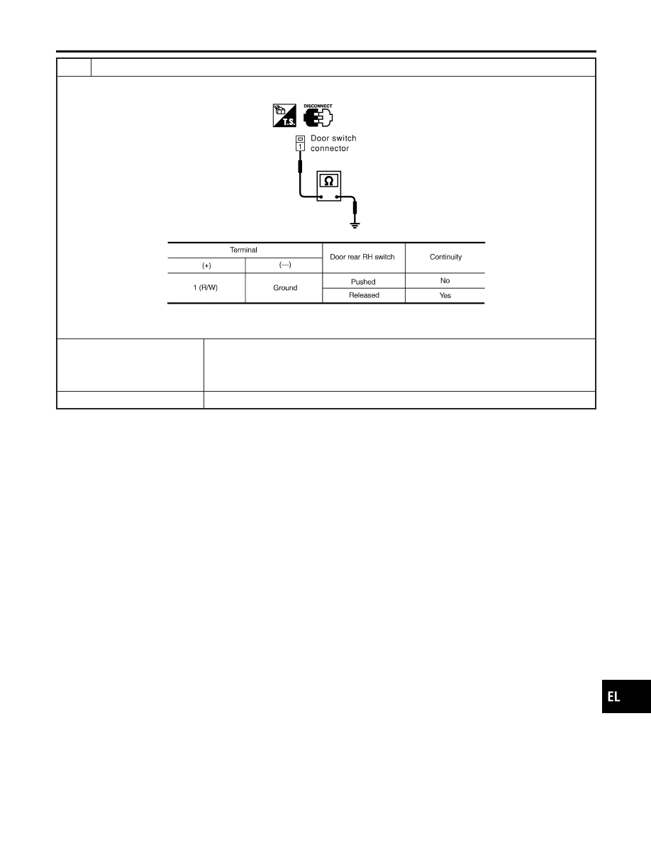
CHECK DOOR SWITCH
Check continuity between door switch rear RH harness connector B41 terminal 1 (R/W) and ground.
SIIA1595E
MTBL1694
OK or NG
OK
©
Check the following.
I
Door switch rear RH ground condition
I
Harness for open or short between smart entrance control unit and door switch rear
RH
NG
©
Replace door switch rear RH.
GI
MA
EM
LC
EC
FE
CL
MT
AT
AX
SU
BR
ST
RS
BT
HA
SC
IDX
POWER DOOR LOCK
Trouble Diagnosis (Cont’d)
EL-289