Almera Tino V10 (2003 year). Manual - part 135
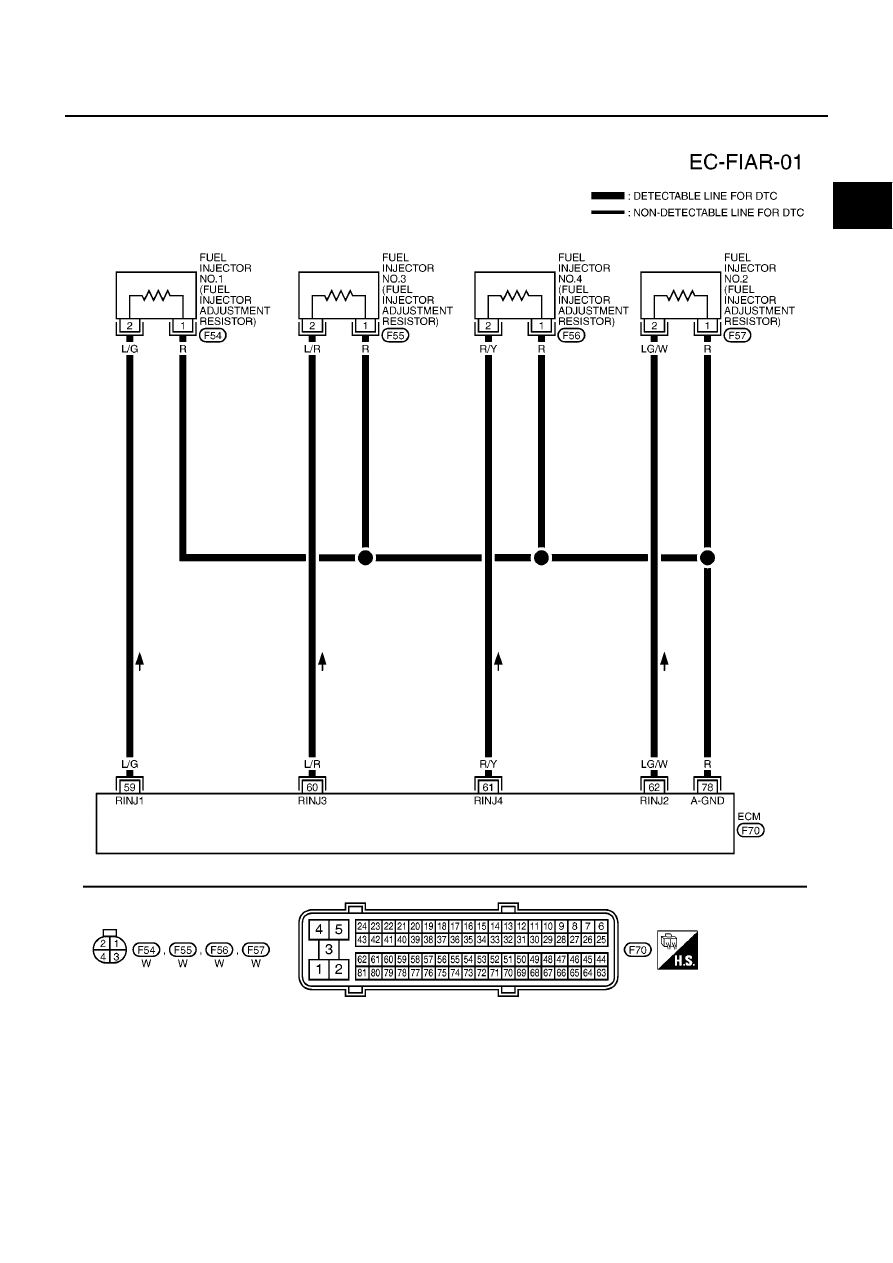
DTC P1260 - P1267 FUEL INJECTOR ADJUSTMENT RESISTOR
EC-1179
[YD (WITH EURO-OBD)]
C
D
E
F
G
H
I
J
K
L
M
A
EC
Wiring Diagram
EBS013FJ
MBWA0631E
|
|
|
DTC P1260 - P1267 FUEL INJECTOR ADJUSTMENT RESISTOR EC-1179 [YD (WITH EURO-OBD)] C D E F G H I J K L M A EC Wiring Diagram EBS013FJ MBWA0631E |