Almera Tino V10 (2003 year). Manual - part 126


  Index      Manuals     Almera Tino V10 (2003 year) - Service and Repair Manual


Search            copyright infringement  


Content      ..     124      125      126      127     ..


Almera Tino V10 (2003 year). Manual - part 126


DTC P0101 MAF SENSOR

EC-1035

[YD (WITH EURO-OBD)]

C

D

E

F

G

H

I

J

K

L

M

A

EC

7.

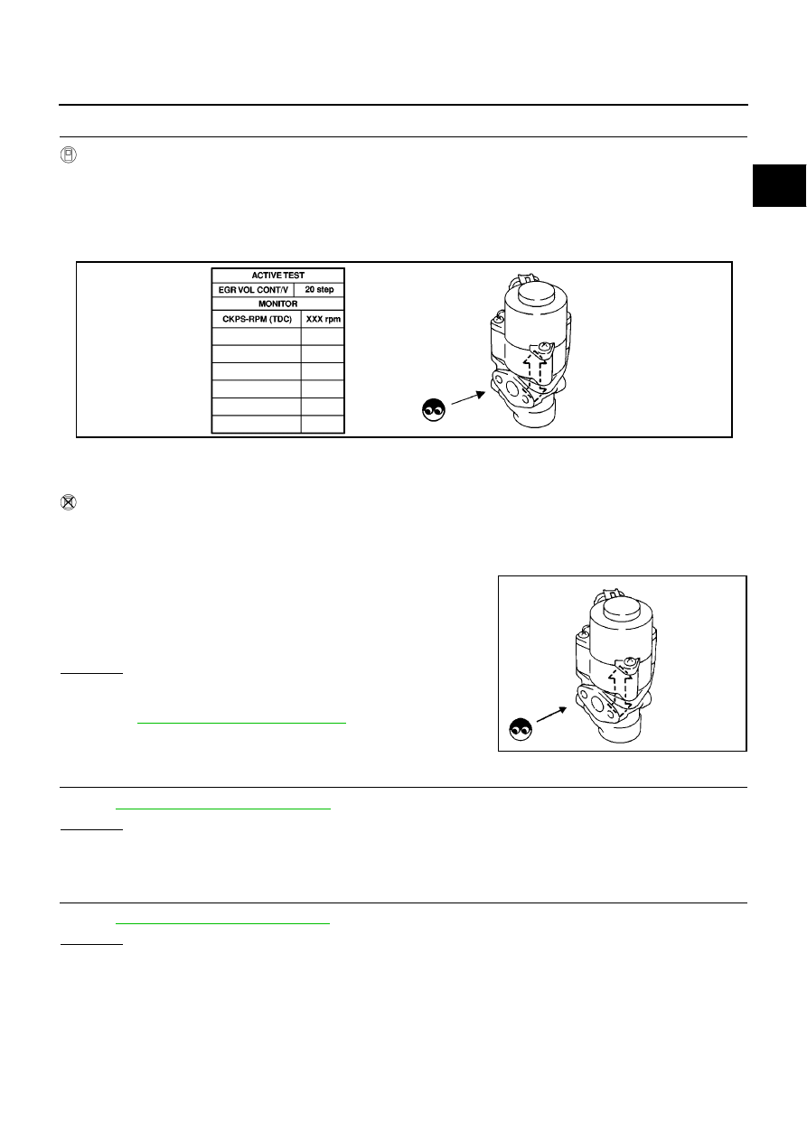
CHECK EGR VOLUME CONTROL VALVE FUNCTION

With CONSULT-II

1.

Reconnect all harness connectors disconnected.

2.

Remove EGR volume control valve from cylinder head.

3.

Turn ignition switch ON.

4.

Perform “EGR VOL CONT/V” in “ACTIVE TEST” mode with CONSULT-II. Check that EGR volume control
valve shaft moves smoothly forward and backward according to the valve opening.

NOTE:
When installing the EGR volume control valve, make sure that the shaft is in the same position before
checking.

Without CONSULT-II

1.

Reconnect all harness connectors disconnected.

2.

Remove EGR volume control valve from cylinder head.

3.

Turn ignition switch ON and OFF.

4.

Check that EGR volume control valve shaft moves smoothly for-
ward and backward according to the ignition switch position.

NOTE:
When installing the EGR volume control valve, make sure that
the shaft is in the same position before checking.

OK or NG

OK

>> GO TO 8.

NG

>> Check EGR volume control valve and its circuit. Refer to

EC-1146, "Diagnostic Procedure"

.

8.

CHECK INTAKE AIR TEMPERATURE SENSOR

Refer to

EC-1045, "Component Inspection"

.

OK or NG

OK

>> GO TO 9.

NG

>> Replace mass sir flow sensor (with intake air temperature sensor).

9.

CHECK TURBOCHARGER BOOST SENSOR

Refer to

EC-1105, "Component Inspection"

.

OK or NG

OK

>> GO TO 10.

NG

>> Replace turbocharger boost sensor.

SEF819Y

SEF560W

EC-1036

[YD (WITH EURO-OBD)]

DTC P0101 MAF SENSOR

10.

CHECK MASS AIR FLOW SENSOR

Refer to

EC-1036, "Component Inspection"

.

OK or NG

OK

>> GO TO 11.

NG

>> Replace mass air flow sensor.

11.

CHECK INTERMITTENT INCIDENT

Refer to

EC-1002, "TROUBLE DIAGNOSIS FOR INTERMITTENT INCIDENT"

.

>> INSPECTION END

Component Inspection

EBS0139P

MASS AIR FLOW SENSOR

1.

Reconnect harness connectors disconnected.

2.

Start engine and warm it up to normal operating temperature.

3.

Check voltage between ECM terminal 54 (Mass air flow sensor
signal) and ground.

4.

If the voltage is out of specification, disconnect MAF sensor har-
ness connector and connect it again.
Then repeat above check.

Removal and Installation

EBS0139Q

MASS AIR FLOW SENSOR

Refer to

EM-119, "AIR CLEANER AND AIR DUCT"

.

Condition

Voltage V

Ignition switch ON (Engine stopped.)

Approx. 0.7

Idle (Engine is warmed up to normal
operating temperature.)

1.8 - 2.3

2,000 rpm (Engine is warmed up to
normal operating temperature.)

2.5 - 3.0

SEF865T

DTC P0102, P0103 MAF SENSOR

EC-1037

[YD (WITH EURO-OBD)]

C

D

E

F

G

H

I

J

K

L

M

A

EC

DTC P0102, P0103 MAF SENSOR

PFP:22680

Component Description

EBS0139R

The mass air flow sensor is placed in the stream of intake air. It mea-
sures the intake flow rate by measuring a part of the entire intake
flow. The mass air flow sensor controls the temperature of the hot
wire to a certain amount. The heat generated by the hot wire is
reduced as the intake air flows around it. The more air, the greater
the heat loss.
Therefore, the electric current supplied to hot wire is changed to
maintain the temperature of the hot wire as air flow increases. The
ECM detects the air flow by means of this current change.

CONSULT-II Reference Value in Data Monitor Mode

EBS0139S

Specification data are reference values.

*: This signal is converted by ECM internally. Thus, it differs from ECM terminal voltage.

ECM Terminals and Reference Value

EBS0139T

Specification data are reference values, and are measured between each terminal and ground.

CAUTION:

Do not use ECM ground terminals when measuring input/output voltage. Doing so may result in dam-
age to the ECM's transistor. Use a ground other than ECM terminals, such as the ground.

PBIB1604E

MONITOR ITEM

CONDITION

SPECIFICATION

MAS AIR/FL SE*

Engine: After warming up

Air conditioner switch: OFF

Shift lever: Neutral position

No-load

Idle

1.5 - 2.0V

2,000 rpm

2.2 - 2.7V

TERMI-

NAL

NO.

WIRE

COLOR

ITEM

CONDITION

DATA

(DC Voltage)

54

W/L

Mass air flow sensor

[Engine is running]

Warm-up condition

Idle speed

1.8 - 2.3V

[Engine is running]

Warm-up condition

Engine speed is 2,000 rpm

2.5 - 3.0V

67

B

Sensor ground
(Sensors shield circuit)

[Ignition switch ON]

Approximately 0.3V

73

O/L

Mass air flow sensor ground

[Ignition switch ON]

Approximately 0.3V

105
113

G
G

ECM relay (self-shutoff)

[Ignition switch ON]
[Ignition switch OFF]

For a few seconds after turning ignition
switch OFF

Approximately 1.2V

[Ignition switch OFF]

More than a few seconds after turning
ignition switch OFF

BATTERY VOLTAGE
(11 - 14V)

119
120

R
R

Power supply for ECM

[Ignition switch ON]

BATTERY VOLTAGE
(11 - 14V)

EC-1038

[YD (WITH EURO-OBD)]

DTC P0102, P0103 MAF SENSOR

On Board Diagnosis Logic

EBS0139U

DTC Confirmation Procedure

EBS0139V

NOTE:
If DTC Confirmation Procedure has been previously conducted, always turn ignition switch OFF and wait at
least 10 seconds before conducting the next test.

WITH CONSULT-II

1.

Turn ignition switch ON.

2.

Select “DATA MONITOR” mode with CONSULT-II.

3.

Wait at least 5 seconds.

4.

If 1st trip DTC is detected, go to

EC-1040, "Diagnostic Proce-

dure"

.

WITH GST

Follow the procedure “WITH CONSULT-II” above.

DTC No.

Trouble diagnosis name

DTC detecting condition

Possible cause

P0102

Mass air flow sensor circuit
low input

An excessively low voltage from the sensor is
sent to ECM.

Harness or connectors
(The sensor circuit is open or shorted.)

Mass air flow sensor

P0103

Mass air flow sensor circuit
high input

An excessively high voltage from the sensor is
sent to ECM.

SEF817Y

DTC P0102, P0103 MAF SENSOR

EC-1039

[YD (WITH EURO-OBD)]

C

D

E

F

G

H

I

J

K

L

M

A

EC

Wiring Diagram

EBS0139W

MBWA0651E

EC-1040

[YD (WITH EURO-OBD)]

DTC P0102, P0103 MAF SENSOR

Diagnostic Procedure

EBS0139X

1.

CHECK GROUND CONNECTIONS

1.

Turn ignition switch OFF.

2.

Loosen and retighten body ground screw. Refer to

EC-1010,

"Ground Inspection"

.

OK or NG

OK

>> GO TO 2.

NG

>> Repair or replace ground connection.

2.

CHECK MAFS POWER SUPPLY CIRCUIT

1.

Disconnect mass air flow sensor harness connector.

2.

Turn ignition switch ON.

3.

Check voltage between mass air flow sensor terminal 5 and
ground with CONSULT-II or tester.

OK or NG

OK

>> GO TO 4.

NG

>> GO TO 3.

3.

DETECT MALFUNCTIONING PART

Check the following.

Harness connectors F45, M71

Harness for open or short between mass air flow sensor and ECM relay

Harness for open or short between mass air flow sensor and ECM

>> Repair open circuit or short to ground or short to power in harness or connectors.

MBIB0915E

MBIB0914E

Voltage: Battery voltage

MBIB0988E

DTC P0102, P0103 MAF SENSOR

EC-1041

[YD (WITH EURO-OBD)]

C

D

E

F

G

H

I

J

K

L

M

A

EC

4.

CHECK MAFS GROUND CIRCUIT FOR OPEN AND SHORT

1.

Turn ignition switch OFF.

2.

Disconnect ECM harness connector.

3.

Check harness continuity between mass air flow sensor terminal 4 and ECM terminal 73.
Refer to Wiring Diagram.

4.

Also check harness for short to ground and short to power.

OK or NG

OK

>> GO TO 5.

NG

>> Repair open circuit or short to ground or short to power in harness or connectors.

5.

CHECK MAFS INPUT SIGNAL CIRCUIT FOR OPEN AND SHORT

1.

Check harness continuity between mass air flow sensor terminal 3 and ECM terminal 54.
Refer to Wiring Diagram.

2.

Also check harness for short to ground and short to power.

OK or NG

OK

>> GO TO 6.

NG

>> Repair open circuit or short to ground or short to power in harness or connectors.

6.

CHECK MASS AIR FLOW SENSOR

Refer to

EC-1041, "Component Inspection"

.

OK or NG

OK

>> GO TO 7.

NG

>> Replace mass air flow sensor.

7.

CHECK INTERMITTENT INCIDENT

Refer to

EC-1002, "TROUBLE DIAGNOSIS FOR INTERMITTENT INCIDENT"

.

>> INSPECTION END

Component Inspection

EBS0139Y

MASS AIR FLOW SENSOR

1.

Reconnect harness connectors disconnected.

2.

Start engine and warm it up to normal operating temperature.

3.

Check voltage between ECM terminal 54 (Mass air flow sensor
signal) and ground.

4.

If the voltage is out of specification, disconnect MAF sensor har-
ness connector and connect it again.
Then repeat above check.

Removal and Installation

EBS0139Z

MASS AIR FLOW SENSOR

Refer to

EM-119, "AIR CLEANER AND AIR DUCT"

.

Continuity should exist.

Continuity should exist.

Condition

Voltage V

Ignition switch ON (Engine stopped.)

Approx. 0.7

Idle (Engine is warmed up to normal
operating temperature.)

1.8 - 2.3

2,000 rpm (Engine is warmed up to
normal operating temperature.)

2.5 - 3.0

SEF865T

EC-1042

[YD (WITH EURO-OBD)]

DTC P0112, P0113 IAT SENSOR

DTC P0112, P0113 IAT SENSOR

PFP:22630

Component Description

EBS013A0

The intake air temperature sensor is built into mass air flow sensor.
The sensor detects intake air temperature and transmits a signal to
the ECM.
The temperature sensing unit uses a thermistor which is sensitive to
the change in temperature. Electrical resistance of the thermistor
decreases in response to the temperature rise.

<Reference data>

*: This data is reference value and is measured between ECM terminal 55 (Intake air
temperature sensor) and ground.

CAUTION:

Do not use ECM ground terminals when measuring input/output
voltage. Doing so may result in damage to the ECM's transistor. Use a ground other than ECM termi-
nals, such as the ground.

On Board Diagnosis Logic

EBS013A1

DTC Confirmation Procedure

EBS013A2

NOTE:
If DTC Confirmation Procedure has been previously conducted, always turn ignition switch OFF and wait at
least 10 seconds before conducting the next test.

WITH CONSULT-II

1.

Turn ignition switch ON.

2.

Select “DATA MONITOR” mode with CONSULT-II.

3.

Wait at least 5 seconds.

4.

If 1st trip DTC is detected, go to

EC-1044, "Diagnostic Proce-

dure"

.

WITH GST

Follow the procedure “WITH CONSULT-II” above.

PBIB1604E

Intake air

temperature

°

C (

°

F)

Voltage*

V

Resistance

k

10 (14)

4.73

7.9 - 9.3

25 (77)

3.62

1.9 - 2.1

80 (176)

1.53

0.31 - 0.37

SEF012P

DTC No.

Trouble diagnosis name

DTC detecting condition

Possible cause

P0112

Intake air temperature sensor
circuit low input

An excessively low voltage from the sensor
is sent to ECM.

Harness or connectors
(The sensor circuit is open or shorted.)

Intake air temperature sensor

P0113

Intake air temperature sensor
circuit high input

An excessively high voltage from the sensor
is sent to ECM.

SEF817Y

DTC P0112, P0113 IAT SENSOR

EC-1043

[YD (WITH EURO-OBD)]

C

D

E

F

G

H

I

J

K

L

M

A

EC

Wiring Diagram

EBS013A3

YEC497A

EC-1044

[YD (WITH EURO-OBD)]

DTC P0112, P0113 IAT SENSOR

Diagnostic Procedure

EBS013A4

1.

CHECK GROUND CONNECTIONS

1.

Turn ignition switch OFF.

2.

Loosen and retighten body ground screw. Refer to

EC-1010,

"Ground Inspection"

.

OK or NG

OK

>> GO TO 2.

NG

>> Repair or replace ground connection.

2.

CHECK INTAKE AIR TEMPERATURE SENSOR POWER SUPPLY CIRCUIT

1.

Disconnect mass air flow sensor (intake air temperature sensor
is built-into) harness connector.

2.

Turn ignition switch ON.

3.

Check voltage between MAF sensor terminal 2 and ground with
CONSULT-II or tester.

OK or NG

OK

>> GO TO 3.

NG

>> Repair harness or connectors.

3.

CHECK INTAKE AIR TEMPERATURE SENSOR GROUND CIRCUIT FOR OPEN AND SHORT

1.

Turn ignition switch OFF.

2.

Disconnect ECM harness connector.

3.

Check harness continuity between MAF sensor terminal 1 and ECM terminal 74.
Refer to Wiring Diagram.

4.

Also check harness for short to ground and short to power.

OK or NG

OK

>> GO TO 4.

NG

>> Repair open circuit or short to ground or short to power in harness or connectors.

MBIB0915E

MBIB0914E

Voltage: Approximately 5.3V

MBIB0989E

Continuity should exist.

DTC P0112, P0113 IAT SENSOR

EC-1045

[YD (WITH EURO-OBD)]

C

D

E

F

G

H

I

J

K

L

M

A

EC

4.

CHECK INTAKE AIR TEMPERATURE SENSOR

Refer to

EC-1045, "Component Inspection"

.

OK or NG

OK

>> GO TO 5.

NG

>> Replace mass air flow sensor (with intake air temperature sensor).

5.

CHECK INTERMITTENT INCIDENT

Refer to

EC-1002, "TROUBLE DIAGNOSIS FOR INTERMITTENT INCIDENT"

.

>> INSPECTION END

Component Inspection

EBS013A5

INTAKE AIR TEMPERATURE SENSOR

1.

Check resistance between mass air flow sensor terminals 1 and
2 under the following conditions.

2.

If NG, replace mass air flow sensor (with intake air temperature
sensor).

Removal and Installation

EBS013A6

MASS AIR FLOW SENSOR

Refer to

EM-119, "AIR CLEANER AND AIR DUCT"

.

Intake air temperature

°

C (

°

F)

Resistance k

25 (77)

1.9 - 2.1

PBIB1604E

SEF012P

EC-1046

[YD (WITH EURO-OBD)]

DTC P0117, P0118 ECT SENSOR

DTC P0117, P0118 ECT SENSOR

PFP:22630

Description

EBS013A7

The engine coolant temperature sensor is used to detect the engine
coolant temperature. The sensor modifies a voltage signal from the
ECM. The modified signal returns to the ECM as the engine coolant
temperature input. The sensor uses a thermistor which is sensitive to
the change in temperature. The electrical resistance of the ther-
mistor decreases as temperature increases.

<Reference data>

*: This data is reference value and is measured between ECM terminal 51 (Engine
coolant temperature sensor) and ground.

CAUTION:

Do not use ECM ground terminals when measuring input/output voltage. Doing so may result in dam-
age to the ECM's transistor. Use a ground other than ECM terminals, such as the ground.

On Board Diagnosis Logic

EBS013A8

DTC Confirmation Procedure

EBS013A9

NOTE:
If DTC Confirmation Procedure has been previously conducted, always turn ignition switch OFF and wait at
least 10 seconds before conducting the next test.

WITH CONSULT-II

1.

Turn ignition switch ON.

2.

Select “DATA MONITOR” mode with CONSULT-II.

3.

Wait at least 5 seconds.

4.

If 1st trip DTC is detected, go to

EC-1048, "Diagnostic Proce-

dure"

.

WITH GST

Follow the procedure “WITH CONSULT-II” above.

SEF594K

Engine coolant tempera-

ture

°

C (

°

F)

Voltage* (V)

Resistance (k

)

10 (14)

4.7

7.0 - 11.4

20 (68)

3.8

2.1 - 2.9

50 (122)

2.6

0.68 - 1.00

90 (194)

1.3

0.236 - 0.260

SEF012P

DTC No.

Trouble diagnosis name

DTC detecting condition

Possible cause

P0117

Engine coolant temperature
sensor circuit low input

An excessively low voltage from the sensor
is sent to ECM.

Harness or connectors
(The sensor circuit is open or shorted.)

Engine coolant temperature sensor

P0118

Engine coolant temperature
sensor circuit high input

An excessively high voltage from the sensor
is sent to ECM.

SEF817Y

DTC P0117, P0118 ECT SENSOR

EC-1047

[YD (WITH EURO-OBD)]

C

D

E

F

G

H

I

J

K

L

M

A

EC

Wiring Diagram

EBS013AA

YEC498A

EC-1048

[YD (WITH EURO-OBD)]

DTC P0117, P0118 ECT SENSOR

Diagnostic Procedure

EBS013AB

1.

CHECK GROUND CONNECTIONS

1.

Turn ignition switch OFF.

2.

Loosen and retighten body ground screw. Refer to

EC-1010,

"Ground Inspection"

.

OK or NG

OK

>> GO TO 2.

NG

>> Repair or replace ground connection.

2.

CHECK ECT SENSOR POWER SUPPLY CIRCUIT

1.

Disconnect engine coolant temperature (ECT) sensor harness
connector.

2.

Turn ignition switch ON.

3.

Check voltage between ECT sensor terminal 1 and ground with
CONSULT-II or tester.

OK or NG

OK

>> GO TO 3.

NG

>> Repair harness or connectors.

3.

CHECK ECT SENSOR GROUND CIRCUIT FOR OPEN AND SHORT

1.

Turn ignition switch OFF.

2.

Disconnect ECM harness connector.

3.

Check harness continuity between ECT sensor terminal 2 and ECM terminal 70.
Refer to Wiring Diagram.

4.

Also check harness for short to ground and short to power.

OK or NG

OK

>> GO TO 4.

NG

>> Repair open circuit or short to ground or short to power in harness or connectors.

MBIB0915E

MBIB0908E

Voltage: Approximately 5.3V

PBIB0152E

Continuity should exist.

DTC P0117, P0118 ECT SENSOR

EC-1049

[YD (WITH EURO-OBD)]

C

D

E

F

G

H

I

J

K

L

M

A

EC

4.

CHECK ENGINE COOLANT TEMPERATURE SENSOR

Refer to

EC-1049, "Component Inspection"

.

OK or NG

OK

>> GO TO 5.

NG

>> Replace engine coolant temperature sensor.

5.

CHECK INTERMITTENT INCIDENT

Refer to

EC-1002, "TROUBLE DIAGNOSIS FOR INTERMITTENT INCIDENT"

.

>> INSPECTION END

Component Inspection

EBS013AC

ENGINE COOLANT TEMPERATURE SENSOR

1.

Check resistance between engine coolant temperature sensor
terminals 1 and 2 as shown in the figure.

<Reference data>

2.

If NG, replace engine coolant temperature sensor.

Removal and Installation

EBS013AD

ENGINE COOLANT TEMPERATURE SENSOR

Refer to

EM-186, "CYLINDER HEAD"

.

PBIB2005E

Engine coolant temperature

°

C (

°

F)

Resistance k

20 (68)

2.1 - 2.9

50 (122)

0.68 - 1.00

90 (194)

0.236 - 0.260

SEF012P

EC-1050

[YD (WITH EURO-OBD)]

DTC P0122, P0123 APP SENSOR

DTC P0122, P0123 APP SENSOR

PFP:18002

Description

EBS013AE

The accelerator pedal position sensor is installed on the upper end
of the accelerator pedal assembly. The ECM uses the signal to
determine the amount of fuel to be injected.

CONSULT-II Reference Value in Data Monitor Mode

EBS013AF

Specification data are reference values.

*: This signal is converted by ECM internally. Thus, it differs from ECM terminal voltage.

ECM Terminals and Reference Value

EBS013AG

Specification data are reference values and are measured between each terminal and ground.

CAUTION:

Do not use ECM ground terminals when measuring input/output voltage. Doing so may result in dam-
age to the ECM's transistor. Use a ground other than ECM terminals, such as the ground.

PBIB1741E

MONITOR ITEM

CONDITION

SPECIFICATION

ACCEL POS SEN*

Ignition switch: ON
(Engine stopped)

Accelerator pedal: fully released

0.2 - 0.7V

Accelerator pedal: fully depressed

3.9 - 4.9V

ACCEL SEN 2*

Ignition switch: ON
(Engine stopped)

Accelerator pedal: fully released

0.1 - 0.4V

Accelerator pedal: fully depressed

1.9 - 2.4V

TERMI-

NAL

NO.

WIRE

COLOR

ITEM

CONDITION

DATA

(DC Voltage)

82

L

Accelerator pedal position
sensor 1 power supply

[Ignition switch ON]

Approximately 5.3V

83

L/R

Accelerator pedal position
sensor 1

[Ignition switch ON]

Engine stopped

Accelerator pedal: Fully released

0.5 - 1.0V

[Ignition switch ON]

Engine stopped

Accelerator pedal: Fully depressed

4.2 - 5.2V

84

L/W

Accelerator pedal position
sensor 1 ground

[Ignition switch ON]

Approximately 0.3V

85

Sensor ground
(Accelerator pedal position
sensor shield circuit)

[Ignition switch ON]

Approximately 0.3V

90

R

Accelerator pedal position
sensor 2 power supply

[Ignition switch ON]

Approximately 5.3V


Content      ..     124      125      126      127     ..