Almera Tino V10 (2003 year). Manual - part 125


  Index      Manuals     Almera Tino V10 (2003 year) - Service and Repair Manual


Search            copyright infringement  


Content      ..     123      124      125      126     ..


Almera Tino V10 (2003 year). Manual - part 125


DTC P0045 TC BOOST CONTROL SOLENOID VALVE

EC-1019

[YD (WITH EURO-OBD)]

C

D

E

F

G

H

I

J

K

L

M

A

EC

Diagnostic Procedure

EBS01393

1.

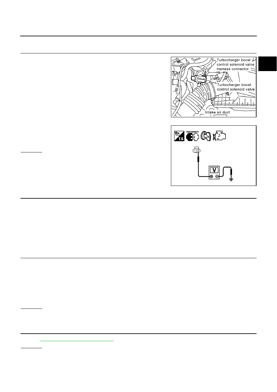
CHECK TURBOCHARGER BOOST CONTROL SOLENOID VALVE POWER SUPPLY CIRCUIT

1.

Disconnect turbocharger boost control solenoid valve harness
connector.

2.

Turn ignition switch ON.

3.

Check voltage between turbocharger boost control solenoid
valve terminal 2 and ground with CONSULT-II or tester.

OK or NG

OK

>> GO TO 3.

NG

>> GO TO 2.

2.

DETECT MALFUNCTIONING PART

Check the following.

Harness connectors F45, M71

Harness for open and short between turbocharger boost control solenoid valve and ECM relay

Harness for open and short between turbocharger boost control solenoid valve and ECM

>> Repair open circuit or short to ground or short to power in harness or connectors.

3.

CHECK TURBOCHARGER BOOST CONTROL SOLENOID VALVE OUTPUT SIGNAL CIRCUIT FOR

OPEN AND SHORT

1.

Turn ignition switch OFF.

2.

Disconnect ECM harness connector.

3.

Check harness continuity between ECM terminal 6 and turbocharger boost control solenoid valve terminal
1. Refer to Wiring Diagram.

4.

Also check harness for short to ground and short to power.

OK or NG

OK

>> GO TO 4.

NG

>> Repair open circuit or short to ground or short to power in harness or connectors.

4.

CHECK TURBOCHARGER BOOST CONTROL SOLENOID VALVE

Refer to

EC-1020, "Component Inspection"

.

OK or NG

OK

>> GO TO 5.

NG

>> Replace turbocharger boost control solenoid valve.

MBIB0921E

Voltage: Battery voltage

MBIB0010E

Continuity should exist.

EC-1020

[YD (WITH EURO-OBD)]

DTC P0045 TC BOOST CONTROL SOLENOID VALVE

5.

CHECK INTERMITTENT INCIDENT

Refer to

EC-1002, "TROUBLE DIAGNOSIS FOR INTERMITTENT INCIDENT"

.

>> INSPECTION END

Component Inspection

EBS01394

TURBOCHARGER BOOST CONTROL SOLENOID VALVE

1.

Disconnect turbocharger boost control solenoid valve harness
connector.

2.

Apply 12V direct current between turbocharger boost control
solenoid valve terminals.

3.

Check air passage continuity of turbocharger boost control sole-
noid valve under the following conditions.

Operation takes less than 1 second.

If NG, replace turbocharger boost control solenoid valve.

MBIB0921E

CONDITIONS

Air passage continuity

between and B

Air passage continuity

between and C

12V direct current supply
between terminals and 2

Yes

No

No supply

No

Yes

MBIB0996E

DTC P0088 FUEL SYSTEM

EC-1021

[YD (WITH EURO-OBD)]

C

D

E

F

G

H

I

J

K

L

M

A

EC

DTC P0088 FUEL SYSTEM

PFP:17520

On Board Diagnosis Logic

EBS01395

DTC Confirmation Procedure

EBS01396

NOTE:
If DTC Confirmation Procedure has been previously conducted, always turn ignition switch OFF and wait at
least 10 seconds before conducting the next test.

WITH CONSULT-II

1.

Start engine and warm it up to normal operating temperature.

2.

Select “DATA MONITOR” mode with CONSULT-II.

3.

Keep engine speed more than 2,000 rpm for at least 20 sec-
onds.

4.

If 1st trip DTC is detected, go to

EC-1021, "Diagnostic Proce-

dure"

.

WITH GST

Follow the procedure “WITH CONSULT-II” above.

Diagnostic Procedure

EBS01397

1.

CHECK FUEL RAIL PRESSURE SENSOR

Refer to

EC-1063, "Component Inspection"

.

OK or NG

OK

>> GO TO 2.

NG

>> Replace fuel rail.

2.

CHECK FUEL INJECTOR

Refer to

EC-1071, "Component Inspection"

.

OK or NG

OK

>> GO TO 3.

NG

>> Replace fuel injector.

3.

CHECK FUEL PUMP

Refer to

EC-1161, "Component Inspection"

.

OK or NG

OK

>> GO TO 5.

NG

>> GO TO 4.

DTC No.

Trouble diagnosis name

DTC detecting condition

Possible cause

P0088

Fuel rail pressure too high

Fuel pressure is too much higher than the
specified value.

Fuel pump

Fuel injector

Fuel rail pressure sensor

SEF817Y

EC-1022

[YD (WITH EURO-OBD)]

DTC P0088 FUEL SYSTEM

4.

REPLACE FUEL PUMP

1.

Replace fuel pump.

2.

Perform Fuel Pump Learning Value Clearing. Refer to

EC-956, "Fuel Pump Learning Value Clearing"

.

>> INSPECTION END

5.

CHECK INTERMITTENT INCIDENT

Refer to

EC-1002, "TROUBLE DIAGNOSIS FOR INTERMITTENT INCIDENT"

.

>> INSPECTION END

Removal and Installation

EBS01398

FUEL INJECTOR

Refer to

EM-147, "INJECTION TUBE AND FUEL INJECTOR"

.

FUEL PUMP

Refer to

EM-150, "FUEL PUMP"

.

DTC P0089 FUEL PUMP

EC-1023

[YD (WITH EURO-OBD)]

C

D

E

F

G

H

I

J

K

L

M

A

EC

DTC P0089 FUEL PUMP

PFP:16700

On Board Diagnosis Logic

EBS01399

DTC Confirmation Procedure

EBS0139A

NOTE:
If DTC Confirmation Procedure has been previously conducted, always turn ignition switch OFF and wait at
least 10 seconds before conducting the next test.

WITH CONSULT-II

1.

Start engine and warm it up to normal operating temperature.

2.

Select “DATA MONITOR” mode with CONSULT-II.

3.

Let engine idle for at least 30 seconds.

4.

If 1st trip DTC is detected, go to

EC-1024, "Diagnostic Proce-

dure"

.

WITH GST

Follow the procedure “WITH CONSULT-II” above.

DTC No.

Trouble diagnosis name

DTC detecting condition

Possible cause

P0089

Fuel pump performance

Fuel pressure is too much higher than the target value.

Fuel pump

Air mixed with fuel

Lack of fuel

Fuel rail pressure sensor

SEF817Y

EC-1024

[YD (WITH EURO-OBD)]

DTC P0089 FUEL PUMP

Diagnostic Procedure

EBS0139B

1.

PERFORM FUEL PUMP LEARNING VALUE CLEARING

NOTE:
If the DTC is detected because of air mixed with fuel (i.e.: caused by lack of fuel), it may become normal by
performing following procedure.

With CONSULT-II

1.

Turn ignition switch ON.

2.

Perform Fuel Pump Learning value clearing. Refer to

EC-956, "Fuel Pump Learning Value Clearing"

.

3.

Start engine and let it idle for at least 60 seconds.

4.

Select “SELF-DIAG RESULT” mode with CONSULT-II.

5.

Touch “ERASE”.

6.

Perform

EC-1023, "DTC Confirmation Procedure"

, again.

7.

Is 1st trip DTC detected again?

With GST

1.

Turn ignition switch ON.

2.

Perform Fuel Pump Learning value clearing. Refer to

EC-956, "Fuel Pump Learning Value Clearing"

.

3.

Start engine and let it idle for at least 60 seconds.

4.

Select MODE 4 with GST.

5.

Touch “ERASE”.

6.

Perform

EC-1023, "DTC Confirmation Procedure"

, again.

7.

Is 1st trip DTC detected again?

Yes or No

Yes

>> GO TO 2.

No

>> INSPECTION END

2.

CHECK FUEL RAIL PRESSURE SENSOR

Refer to

EC-1063, "Component Inspection"

.

OK or NG

OK

>> GO TO 3.

NG

>> Replace fuel rail.

3.

CHECK FUEL PUMP

Perform

EC-1158, "DTC Confirmation Procedure"

.

OK or NG

OK

>> GO TO 5.

NG

>> GO TO 4.

4.

REPLACE FUEL PUMP

1.

Replace Fuel pump.

2.

Perform Fuel Pump Learning Value Clearing. Refer to

EC-956, "Fuel Pump Learning Value Clearing"

.

>> INSPECTION END

5.

CHECK INTERMITTENT INCIDENT

Refer to

EC-1002, "TROUBLE DIAGNOSIS FOR INTERMITTENT INCIDENT"

.

>> INSPECTION END

DTC P0089 FUEL PUMP

EC-1025

[YD (WITH EURO-OBD)]

C

D

E

F

G

H

I

J

K

L

M

A

EC

Removal and Installation

EBS0139C

FUEL PUMP

Refer to

EM-150, "FUEL PUMP"

.

EC-1026

[YD (WITH EURO-OBD)]

DTC P0093 FUEL SYSTEM

DTC P0093 FUEL SYSTEM

PFP:17520

On Board Diagnosis Logic

EBS0139D

DTC Confirmation Procedure

EBS0139E

NOTE:
If DTC Confirmation Procedure has been previously conducted, always turn ignition switch OFF and wait at
least 10 seconds before conducting the next test.

WITH CONSULT-II

1.

Turn ignition switch ON.

2.

Select “DATA MONITOR” mode with CONSULT-II.

3.

Start engine and keep engine speed more than 4,000 rpm for at
least 5 seconds.

4.

If 1st trip DTC is detected, go to

EC-1027, "Diagnostic Proce-

dure"

.

WITH GST

Follow the procedure “WITH CONSULT-II” above.

DTC No.

Trouble diagnosis name

DTC detecting condition

Possible cause

P0093

Fuel system leak

ECM detects a fuel system leak.
(The relation between the output voltage to the
fuel pump and input voltage from the fuel rail
pressure sensor is out of the normal range.)

Fuel pump

Fuel rail

Fuel pipe

Fuel rail pressure relief valve

Air mixed with fuel

Lack of fuel

SEF817Y

DTC P0093 FUEL SYSTEM

EC-1027

[YD (WITH EURO-OBD)]

C

D

E

F

G

H

I

J

K

L

M

A

EC

Diagnostic Procedure

EBS0139F

1.

PERFORM FUEL PUMP LEARNING VALUE CLEARING

NOTE:
If the DTC is detected because of air mixed with fuel (i.e.: caused by lack of fuel), it may become normal by
performing following procedure.

With CONSULT-II

1.

Turn ignition switch ON.

2.

Perform Fuel Pump Learning value clearing. Refer to

EC-956, "Fuel Pump Learning Value Clearing"

.

3.

Start engine and let it idle for at least 60 seconds.

4.

Select “SELF-DIAG RESULT” mode with CONSULT-II.

5.

Touch “ERASE”.

6.

Perform

EC-1026, "DTC Confirmation Procedure"

, again.

7.

Is 1st trip DTC detected again?

With GST

1.

Turn ignition switch ON.

2.

Perform Fuel Pump Learning value clearing. Refer to

EC-956, "Fuel Pump Learning Value Clearing"

.

3.

Start engine and let it idle for at least 60 seconds.

4.

Select MODE 4 with GST.

5.

Touch “ERASE”.

6.

Perform

EC-1026, "DTC Confirmation Procedure"

, again.

7.

Is 1st trip DTC detected again?

Yes or No

Yes

>> GO TO 2.

No

>> INSPECTION END

2.

CHECK FUEL LINE FOR LEAK

1.

Start engine.

2.

Visually check the following for fuel leak.

Fuel tube from fuel pump to fuel rail

Fuel rail

Fuel tube from fuel rail to fuel injector

3.

Also check for improper connection or pinches.

OK or NG

OK

>> GO TO 3.

NG

>> Repair malfunctioning part.

3.

CHECK FUEL RAIL PRESSURE RELIEF VALVE

Refer to

EC-1028, "Component Inspection"

.

OK or NG

OK

>> GO TO 4.

NG

>> Replace fuel rail.

4.

CHECK INTERMITTENT INCIDENT

Refer to

EC-1002, "TROUBLE DIAGNOSIS FOR INTERMITTENT INCIDENT"

.

OK or NG

OK

>> GO TO 5.

NG

>> Repair or replace.

EC-1028

[YD (WITH EURO-OBD)]

DTC P0093 FUEL SYSTEM

5.

REPLACE FUEL PUMP

1.

Replace fuel pump.

2.

Perform Fuel Pump Learning Value Clearing. Refer to

EC-956, "Fuel Pump Learning Value Clearing"

.

>> INSPECTION END

Component Inspection

EBS0139G

FUEL RAIL PRESSURE RELIEF VALVE

With CONSULT-II

WARNING:

Confirm that the engine is cooled down and there are no fire hazards near the vehicle.

Prepare pans or saucers under the disconnected fuel line because the fuel may spill out.

1.

Turn ignition switch OFF.

2.

Remove fuel hose from fuel rail pressure relief valve.

3.

Attach a blind cap or plug to removed hose.

4.

Turn ignition switch ON.

5.

Select “PRES REGULATOR” in “ACTIVE TEST MODE” with
CONSULT-II.

6.

Start engine and keep engine speed 2,000 rpm.

7.

Raise fuel pressure to 160 MPa with touching “UP” or “Qu” on
the CONSULT-II screen.

8.

Confirm that the fuel does not come out from the fuel rail pres-
sure relief valve.

WARNING:

Be careful not to allow leaked fuel to contaminate engine
compartment. Especially, ensure to keep engine mount
insulator clear of fuel.

If the fuel comes out, stop the engine immediately.

Without CONSULT-II

WARNING:

Confirm that the engine is cooled down and there are no fire hazards near the vehicle.

Prepare pans or saucers under the disconnected fuel line because the fuel may spill out.

1.

Turn ignition switch OFF.

2.

Remove fuel hose from fuel rail pressure relief valve.

3.

Attach a blind cap or plug to removed hose.

4.

Start engine and keep engine speed more than 4,000 rpm for at
least 5 seconds.

5.

Confirm that the fuel does not come out from the fuel rail pres-
sure relief valve.

WARNING:

Be careful not to allow leaked fuel to contaminate engine
compartment. Especially, ensure to keep engine mount
insulator clear of fuel.

If the fuel comes out, stop the engine immediately.

MBIB0910E

PBIB0587E

MBIB0910E

DTC P0093 FUEL SYSTEM

EC-1029

[YD (WITH EURO-OBD)]

C

D

E

F

G

H

I

J

K

L

M

A

EC

Removal and Installation

EBS0139H

FUEL RAIL

Refer to

EM-147, "INJECTION TUBE AND FUEL INJECTOR"

.

FUEL PUMP

Refer to

EM-150, "FUEL PUMP"

.

EC-1030

[YD (WITH EURO-OBD)]

DTC P0101 MAF SENSOR

DTC P0101 MAF SENSOR

PFP:22680

Component Description

EBS0139I

The mass air flow sensor is placed in the stream of intake air. It mea-
sures the intake flow rate by measuring a part of the entire intake
flow. The mass air flow sensor controls the temperature of the hot
wire to a certain amount. The heat generated by the hot wire is
reduced as the intake air flows around it. The more air, the greater
the heat loss.
Therefore, the electric current supplied to hot wire is changed to
maintain the temperature of the hot wire as air flow increases. The
ECM detects the air flow by means of this current change.

CONSULT-II Reference Value in Data Monitor Mode

EBS0139J

Specification data are reference values.

*: This signal is converted by ECM internally. Thus, it differs from ECM terminal voltage.

ECM Terminals and Reference Value

EBS0139K

Specification data are reference values, and are measured between each terminal and ground.

CAUTION:

Do not use ECM ground terminals when measuring input/output voltage. Doing so may result in dam-
age to the ECM's transistor. Use a ground other than ECM terminals, such as the ground.

PBIB1604E

MONITOR ITEM

CONDITION

SPECIFICATION

MAS AIR/FL SE*

Engine: After warming up

Air conditioner switch: OFF

Shift lever: Neutral position

No-load

Idle

1.5 - 2.0V

2,000 rpm

2.2 - 2.7V

TERMI-

NAL

NO.

WIRE

COLOR

ITEM

CONDITION

DATA

(DC Voltage)

54

W/L

Mass air flow sensor

[Engine is running]

Warm-up condition

Idle speed

1.8 - 2.3V

[Engine is running]

Warm-up condition

Engine speed is 2,000 rpm

2.5 - 3.0V

67

B

Sensor ground
(Sensors shield circuit)

[Ignition switch ON]

Approximately 0.3V

73

O/L

Mass air flow sensor ground

[Ignition switch ON]

Approximately 0.3V

105

113

G
G

ECM relay (self-shutoff)

[Ignition switch ON]
[Ignition switch OFF]

For a few seconds after turning ignition
switch OFF

Approximately 1.2V

[Ignition switch OFF]

More than a few seconds after turning
ignition switch OFF

BATTERY VOLTAGE
(11 - 14V)

119

120

R
R

Power supply for ECM

[Ignition switch ON]

BATTERY VOLTAGE
(11 - 14V)

DTC P0101 MAF SENSOR

EC-1031

[YD (WITH EURO-OBD)]

C

D

E

F

G

H

I

J

K

L

M

A

EC

On Board Diagnosis Logic

EBS0139L

DTC Confirmation Procedure

EBS0139M

CAUTION:

Always drive vehicle at a safe speed.

NOTE:
If DTC Confirmation Procedure has been previously conducted, always turn ignition switch OFF and wait at
least 10 seconds before conducting the next test.

WITH CONSULT-II

1.

Turn ignition switch ON.

2.

Select “DATA MONITOR” mode with CONSULT-II.

3.

Start engine and let it idle for at least 40 seconds.

4.

Drive vehicle under the following condition.

5.

Release accelerator pedal for at least 10 seconds.
Do not depress brake pedal during this procedure.

6.

If 1st trip DTC is detected, go to

EC-1033, "Diagnostic Proce-

dure"

.

WITH GST

Follow the procedure “WITH CONSULT-II” above.

DTC No.

Trouble diagnosis name

DTC detecting condition

Possible cause

P0101

Mass air flow sensor circuit
range/performance problem

Improper voltage from the sensor is sent to
ECM compared with the driving condition.

Harness or connectors
(The sensor circuit is open or shorted.)

Mass air flow sensor

Intake air leaks

Air cleaner

EGR volume control valve

Intake air temperature sensor

Turbocharger boost sensor
(YD22DDTi engine models)

CKPS·RPM

Approx. 2800 rpm

VHCL SPEED SE

70 - 100 km/h

Shift lever

4th position

MBIB1085E

EC-1032

[YD (WITH EURO-OBD)]

DTC P0101 MAF SENSOR

Wiring Diagram

EBS0139N

MBWA0651E

DTC P0101 MAF SENSOR

EC-1033

[YD (WITH EURO-OBD)]

C

D

E

F

G

H

I

J

K

L

M

A

EC

Diagnostic Procedure

EBS0139O

1.

CHECK INTAKE SYSTEM

1.

Check air cleaner for clogging.

2.

Check the following for connection and cracks.

Air duct

Vacuum hoses

Intake air passage between air duct and intake manifold

OK or NG

OK

>> GO TO 2.

NG

>> Reconnect or repair the parts.

2.

CHECK GROUND CONNECTIONS

1.

Turn ignition switch OFF.

2.

Loosen and retighten body ground screw. Refer to

EC-1010,

"Ground Inspection"

.

OK or NG

OK

>> GO TO 3.

NG

>> Repair or replace ground connection.

3.

CHECK MAFS POWER SUPPLY CIRCUIT

1.

Disconnect mass air flow sensor harness connector.

2.

Turn ignition switch ON.

3.

Check voltage between mass air flow sensor terminal 5 and
ground with CONSULT-II or tester.

OK or NG

OK

>> GO TO 5.

NG

>> GO TO 4.

MBIB0915E

MBIB0914E

Voltage: Battery voltage

MBIB0988E

EC-1034

[YD (WITH EURO-OBD)]

DTC P0101 MAF SENSOR

4.

DETECT MALFUNCTIONING PART

Check the following.

Harness connectors F45, M71

Harness for open or short between mass air flow sensor and ECM relay

Harness for open or short between mass air flow sensor and ECM

>> Repair open circuit or short to ground or short to power in harness or connectors.

5.

CHECK MAFS GROUND CIRCUIT FOR OPEN AND SHORT

1.

Turn ignition switch OFF.

2.

Disconnect ECM harness connector.

3.

Check harness continuity between mass air flow sensor terminal 4 and ECM terminal 73.
Refer to Wiring Diagram.

4.

Also check harness for short to ground and short to power.

OK or NG

OK

>> GO TO 6.

NG

>> Repair open circuit or short to ground or short to power in harness or connectors.

6.

CHECK MAFS INPUT SIGNAL CIRCUIT FOR OPEN AND SHORT

1.

Check harness continuity between mass air flow sensor terminal 3 and ECM terminal 54.
Refer to Wiring Diagram.

2.

Also check harness for short to ground and short to power.

OK or NG

OK

>> GO TO 7.

NG

>> Repair open circuit or short to ground or short to power in harness or connectors.

Continuity should exist.

Continuity should exist.


Content      ..     123      124      125      126     ..