Almera Tino V10 (2003 year). Manual - part 116
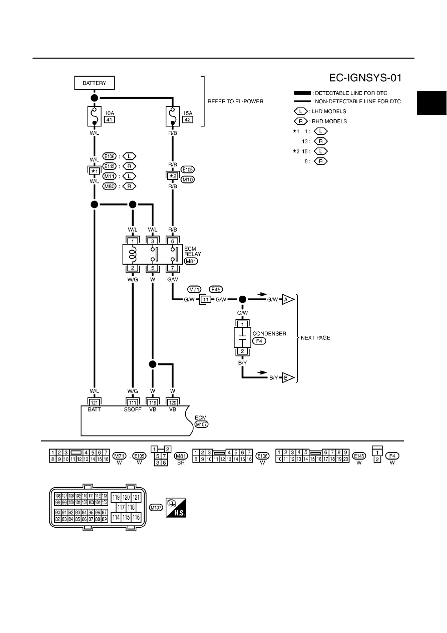
IGNITION SIGNAL
EC-875
[QG (WITHOUT EURO-OBD)]
C
D
E
F
G
H
I
J
K
L
M
A
EC
Wiring Diagram
EBS00R2V
YEC472A
|
|
|
IGNITION SIGNAL EC-875 [QG (WITHOUT EURO-OBD)] C D E F G H I J K L M A EC Wiring Diagram EBS00R2V YEC472A |