Almera Tino V10 (2003 year). Manual - part 114
IAT SENSOR
EC-843
[QG (WITHOUT EURO-OBD)]
C
D
E
F
G
H
I
J
K
L
M
A
EC
4.
CHECK INTAKE AIR TEMPERATURE SENSOR
Refer to
EC-843, "Component Inspection"
.
OK or NG
OK
>> GO TO 5.
NG
>> Replace mass air flow sensor (with intake air temperature sensor).
5.
CHECK INTERMITTENT INCIDENT
Refer to
EC-644, "TROUBLE DIAGNOSIS FOR INTERMITTENT INCIDENT"
.
>> INSPECTION END
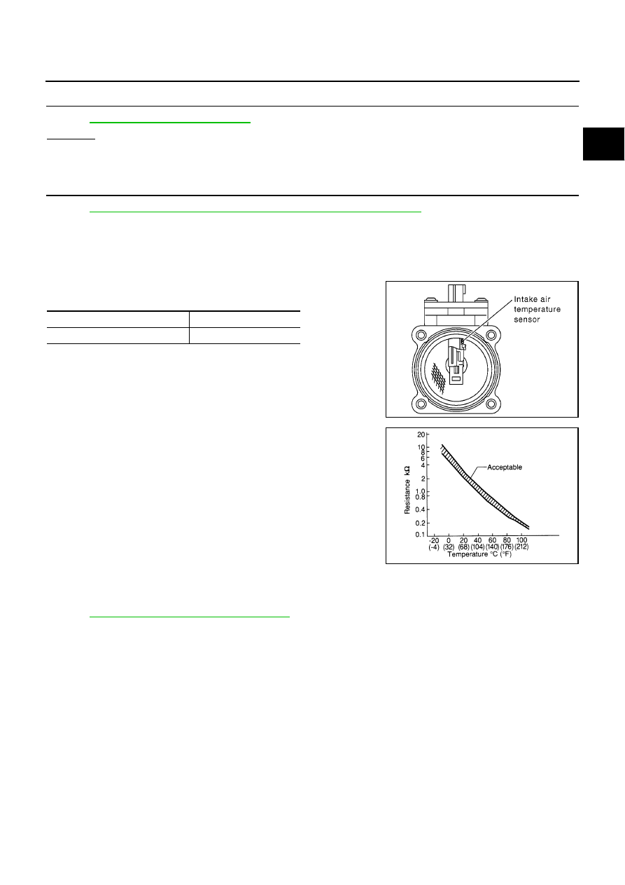
Component Inspection
EBS00R24
INTAKE AIR TEMPERATURE SENSOR
1.
Check resistance between intake air temperature sensor termi-
nals 3 and 5 under the following conditions.
2.
If NG, replace mass air flow sensor (with intake air temperature
sensor).
Removal and Installation
EBS00R25
MASS AIR FLOW SENSOR
Refer to
EM-16, "AIR CLEANER AND AIR DUCT"
.
Intake air temperature
°
C (
°
F)
Resistance k
Ω
25 (77)
1.9 - 2.1
SEC266C
SEF012P