Almera Tino V10 (2003 year). Manual - part 115


  Index      Manuals     Almera Tino V10 (2003 year) - Service and Repair Manual


Search            copyright infringement  


Content      ..     113      114      115      116     ..


Almera Tino V10 (2003 year). Manual - part 115


HO2S1 (A/T MODELS)

EC-859

[QG (WITHOUT EURO-OBD)]

C

D

E

F

G

H

I

J

K

L

M

A

EC

CAUTION:

Discard any heated oxygen sensor which has been dropped from a height of more than 0.5 m (19.7
in) onto a hard surface such as a concrete floor; use a new one.

Before installing new oxygen sensor, clean exhaust system threads using Oxygen Sensor Thread
Cleaner tool J-43897-18 or J-43897-12 and approved anti-seize lubricant.

Without CONSULT-II

1.

Start engine and warm it up to normal operating temperature.
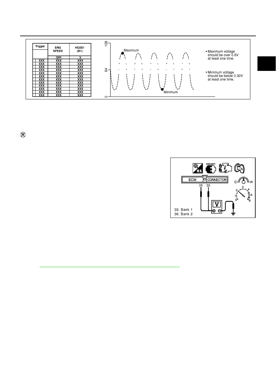
2.

Set voltmeter probes between ECM terminal 35 [HO2S1 (B1) signal] or 36 [HO2S1 (B2) signal] and
engine ground.

3.

Check the following with engine speed held at 2,000 rpm con-
stant under no load.

The voltage fluctuates between 0 to 0.3V and 0.6 to 1.0V
more than 5 times within 10 seconds.

The maximum voltage is over 0.6V at least one time.

The minimum voltage is below 0.3V at least one time.

The voltage never exceeds 1.0V.

1 time: 0 - 0.3V

0.6 - 1.0V

0 - 0.3V

2 times: 0 - 0.3V

0.6 - 1.0V

0 - 0.3V

0.6 - 1.0V

CAUTION:

Discard any heated oxygen sensor which has been dropped
from a height of more than 0.5 m (19.7 in) onto a hard surface such as a concrete floor; use a new
one.

Before installing new oxygen sensor, clean exhaust system threads using Oxygen Sensor Thread
Cleaner tool J-43897-18 or J-43897-12 and approved anti-seize lubricant.

Removal and Installation

EBS00R2H

HEATED OXYGEN SENSOR 1

Refer to

EM-21, "EXHAUST MANIFOLD AND CATALYTIC CONVERTER"

.

SEF648Y

MBIB0019E

EC-860

[QG (WITHOUT EURO-OBD)]

HO2S2 (M/T MODELS)

HO2S2 (M/T MODELS)

PFP:226A0

Component Description

EBS00R2I

The heated oxygen sensor 2, after three way catalyst (manifold),
monitors the oxygen level in the exhaust gas.
Even if switching characteristics of the heated oxygen sensor 1 are
shifted, the air-fuel ratio is controlled to stoichiometric, by the signal
from the heated oxygen sensor 2.
This sensor is made of ceramic zirconia. The zirconia generates volt-
age from approximately 1V in richer conditions to 0V in leaner condi-
tions.
Under normal conditions the heated oxygen sensor 2 is not used for
engine control operation.

CONSULT-II Reference Value in Data Monitor Mode

EBS00R2J

Specification data are reference values.

SEF327R

MONITOR ITEM

CONDITION

SPECIFICATION

HO2S2 (B1)

Engine: After warming up

Keeping the engine speed
between 3,500 and 4,000 rpm
for one minute and at idle for
one minute under no load

Revving engine from idle to 3,000
rpm quickly.

0 - 0.3V

←→

Approx. 0.6 - 1.0V

HO2S2 MNTR (B1)

LEAN

←→

RICH

HO2S2 (M/T MODELS)

EC-861

[QG (WITHOUT EURO-OBD)]

C

D

E

F

G

H

I

J

K

L

M

A

EC

Wiring Diagram

EBS00R2K

YEC485A

EC-862

[QG (WITHOUT EURO-OBD)]

HO2S2 (M/T MODELS)

Specification data are reference values and are measured between each terminal and ground.

CAUTION:

Do not use ECM ground terminals when measuring input/output voltage. Doing so may result in dam-
age to the ECM's transistor. Use a ground other than ECM terminals, such as the ground.

Diagnostic Procedure

EBS00R2L

1.

CHECK OVERALL FUNCTION-I

1.

Start engine and warm it up to the normal operating temperature.

2.

Turn ignition switch “OFF” and wait at least 10 seconds.

3.

Start engine and keep the engine speed between 3,500 and 4,000 rpm for at least one minute under no
load.

4.

Let engine idle for one minute.

5.

Set voltmeter probes between ECM terminal 16 (HO2S2 signal) and ground.

6.

Check the voltage while revving up to 4,000 rpm under no load
at least 10 times. (Depress and release the accelerator pedal as
quickly as possible.)

OK or NG

OK

>> INSPECTION END

NG

>> GO TO 2.

2.

CHECK OVERALL FUNCTION-II

Keep engine at idle for 10 minutes, then check the voltage between
ECM terminal 16 and ground, or check voltage when coasting 80
km/h (50 MPH) in 3rd gear position.

OK or NG

OK

>> INSPECTION END

NG

>> GO TO 3.

TER-

MINAL

NO.

WIRE

COLOR

ITEM

CONDITION

DATA (DC Voltage)

16

W

Heated oxygen sensor 2

[Engine is running]

Warm-up condition

Engine speed is 3,000 rpm quickly after the fol-
lowing conditions are met.

Keeping the engine speed between 3,500 and
4,000 rpm for one minute and at idle for one
minute under no load.

0 - Approximately 1.0V

74

B

Sensors' ground
(Heated oxygen sensor)

[Engine is running]

Idle speed

Approximately 0V

The voltage does not remain in the range of 0.2 to 0.4V

MBIB0020E

The voltage does not remain in the range of 0.2 to 0.4V

MBIB0020E

HO2S2 (M/T MODELS)

EC-863

[QG (WITHOUT EURO-OBD)]

C

D

E

F

G

H

I

J

K

L

M

A

EC

3.

RETIGHTEN GROUND SCREWS

1.

Turn ignition switch “OFF”.

2.

Loosen and retighten engine ground screws.

>> GO TO 4.

4.

CHECK HO2S2 GROUND CIRCUIT FOR OPEN AND SHORT

1.

Turn ignition switch “OFF”.

2.

Disconnect heated oxygen sensor 2 harness connector.

3.

Disconnect ECM harness connector.

4.

Check harness continuity between ECM terminal 74 and HO2S2
terminal 3.
Refer to Wiring Diagram.

5.

Also check harness for short to ground and short to power.

OK or NG

OK

>> GO TO 5.

NG

>> Repair open circuit or short to ground or short to power

in harness or connectors.

5.

CHECK HO2S2 INPUT SIGNAL CIRCUIT FOR OPEN AND SHORT

1.

Check harness continuity between ECM terminal 16 and HO2S2 terminal 2.
Refer to Wiring Diagram.

2.

Check harness continuity between ECM terminal 16 or HO2S2 terminal 2 and ground.
Refer to Wiring Diagram.

3.

Also check harness for short to ground or short to power.

OK or NG

OK

>> GO TO 6.

NG

>> Repair open circuit or short to ground or short to power in harness or connectors.

6.

CHECK HEATED OXYGEN SENSOR 2

Refer to

EC-864, "Component Inspection"

.

OK or NG

OK

>> GO TO 7.

NG

>> Replace heated oxygen sensor 2.

MBIB0095E

Continuity should exist.

MBIB0256E

Continuity should exist.

Continuity should not exist.

EC-864

[QG (WITHOUT EURO-OBD)]

HO2S2 (M/T MODELS)

7.

CHECK INTERMITTENT INCIDENT

Refer to

EC-644, "TROUBLE DIAGNOSIS FOR INTERMITTENT INCIDENT"

.

>> INSPECTION END

Component Inspection

EBS00R2M

HEATED OXYGEN SENSOR 2

With CONSULT-II

1.

Start engine and warm it up to the normal operating temperature.

2.

Turn ignition switch “OFF” and wait at least 10 seconds.

3.

Start engine and keep the engine speed between 3,500 and 4,000 rpm for at least one minute under no
load.

4.

Let engine idle for one minute.

5.

Select “FUEL INJECTION” in “ACTIVE TEST” mode, and select
“HO2S2 (B1)” as the monitor item with CONSULT-II.

6.

Check “HO2S2 (B1)” at idle speed when adjusting “FUEL INJECTION” to

±

25%.

“HO2S2 (B1)” should be above 0.68V at least once when the “FUEL INJECTION” is +25%.
“HO2S2 (B1)” should be below 0.56V at least once when the “FUEL INJECTION” is

25%.

CAUTION:

Discard any heated oxygen sensor which has been dropped from a height of more than 0.5 m (19.7
in) onto a hard surface such as a concrete floor; use a new one.

Before installing new oxygen sensor, clean exhaust system threads using Oxygen Sensor Thread
Cleaner tool J-43897-18 or J-43897-12 and approved anti-seize lubricant.

SEF662Y

SEF244YA

HO2S2 (M/T MODELS)

EC-865

[QG (WITHOUT EURO-OBD)]

C

D

E

F

G

H

I

J

K

L

M

A

EC

Without CONSULT-II

1.

Start engine and warm it up to the normal operating temperature.

2.

Turn ignition switch “OFF” and wait at least 10 seconds.

3.

Start engine and keep the engine speed between 3,500 and 4,000 rpm for at least one minute under no
load.

4.

Let engine idle for one minute.

5.

Set voltmeter probes between ECM terminal 16 (HO2S2 signal) and engine ground.

6.

Check the voltage when revving up to 4,000 rpm under no load
at least 10 times.
(Depress and release accelerator pedal as soon as possible.)
The voltage should be above 0.68V at least once during this
procedure.
If the voltage is above 0.68V at step 6, step 7 is not neces-
sary.

7.

Keep vehicle at idling for 10 minutes, then check voltage. Or
check the voltage when coasting from 80 km/h (50 MPH) in 3rd
gear position.
The voltage should be below 0.56V at least once during this
procedure.

8.

If NG, replace heated oxygen sensor 2.

CAUTION:

Discard any heated oxygen sensor which has been dropped from a height of more than 0.5 m (19.7
in) onto a hard surface such as a concrete floor; use a new one.

Before installing new oxygen sensor, clean exhaust system threads using Oxygen Sensor Thread
Cleaner tool J-43897-18 or J-43897-12 and approved anti-seize lubricant.

Removal and Installation

EBS00R2N

HEATED OXYGEN SENSOR 2

Refer to “EXHAUST SYSTEM”, FE-11.

MBIB0020E

EC-866

[QG (WITHOUT EURO-OBD)]

HO2S2 (A/T MODELS)

HO2S2 (A/T MODELS)

PFP:226A0

Component Description

EBS00R2O

The heated oxygen sensor 2, after three way catalyst (manifold),
monitors the oxygen level in the exhaust gas on each bank.
Even if switching characteristics of the heated oxygen sensor 1 are
shifted, the air-fuel ratio is controlled to stoichiometric, by the signal
from the heated oxygen sensor 2.
This sensor is made of ceramic zirconia. The zirconia generates volt-
age from approximately 1V in richer conditions to 0V in leaner condi-
tions.
Under normal conditions the heated oxygen sensor 2 is not used for
engine control operation.

CONSULT-II Reference Value in Data Monitor Mode

EBS00R2P

Specification data are reference values.

SEF327R

MONITOR ITEM

CONDITION

SPECIFICATION

HO2S2 (B1)
HO2S2 (B2)

Engine: After warming up

Keeping the engine speed at
between 3,500 to 4,000 rpm for
one minute and at idle for one
minute under no load

Revving engine from idle up to
2,000 rpm

0 - 0.3V

←→

Approx. 0.6 - 1.0V

HO2S2 MNTR (B1)
HO2S2 MNTR (B2)

LEAN

←→

RICH

HO2S2 (A/T MODELS)

EC-867

[QG (WITHOUT EURO-OBD)]

C

D

E

F

G

H

I

J

K

L

M

A

EC

Wiring Diagram

EBS00R2Q

BANK 1

YEC486A

EC-868

[QG (WITHOUT EURO-OBD)]

HO2S2 (A/T MODELS)

Specification data are reference values and are measured between each terminal and body ground.

CAUTION:

Do not use ECM ground terminals when measuring input/output voltage. Doing so may result in dam-
age to the ECM's transistor. Use a ground other than ECM terminals, such as the ground.

TER-

MINAL

NO.

WIRE

COLOR

ITEM

CONDITION

DATA (DC Voltage)

16

W

Heated oxygen sensor 2
(bank 1)

[Engine is running]

Warm-up condition

Engine speed is 3,000 rpm quickly after the fol-
lowing conditions are met.

Keeping the engine speed between 3,500 and
4,000 rpm for one minute and at idle for one
minute under no load.

0 - Approximately 1.0V

74

B

Sensors' ground
(Heated oxygen sensor)

[Engine is running]

Idle speed

Approximately 0V

HO2S2 (A/T MODELS)

EC-869

[QG (WITHOUT EURO-OBD)]

C

D

E

F

G

H

I

J

K

L

M

A

EC

BANK 2

YEC487A

EC-870

[QG (WITHOUT EURO-OBD)]

HO2S2 (A/T MODELS)

Specification data are reference values and are measured between each terminal and body ground.

CAUTION:

Do not use ECM ground terminals when measuring input/output voltage. Doing so may result in dam-
age to the ECM's transistor. Use a ground other than ECM terminals, such as the ground.

Diagnostic Procedure

EBS00R2R

1.

CHECK OVERALL FUNCTION - I

1.

Start engine and warm it up to the normal operating temperature.

2.

Turn ignition switch “OFF” and wait at least 10 seconds.

3.

Start engine and keep the engine speed between 3,500 and 4,000 rpm for at least one minute under no
load.

4.

Let engine idle for one minute.

5.

Set voltmeter probes between ECM terminal 16 [HO2S2 (B1) signal] or 17 [HO2S2 (B2) signal] and
ground.

6.

Check the voltage while revving engine up to 4,000 rpm under
no load at least 10 times.
(Depress and release the accelerator pedal as quickly as possi-
ble.)

OK or NG

OK

>> INSPECTION END

NG

>> GO TO 2.

2.

CHECK OVERALL FUNCTION - II

Keep engine at idle for 10 minutes, then check the voltage between
ECM terminal 16 [HO2S2 (B1) signal] or 17 [HO2S2 (B2) signal] and
ground, or check the voltage when coasting at 80 km/h (50 MPH) in
“D” position with OD “OFF”.

OK or NG

OK

>> INSPECTION END

NG

>> GO TO 3.

TER-

MINAL

NO.

WIRE

COLOR

ITEM

CONDITION

DATA (DC Voltage)

17

L

Heated oxygen sensor 2
(bank 2)

[Engine is running]

Warm-up condition

Engine speed is 3,000 rpm quickly after the fol-
lowing conditions are met.

Keeping the engine speed between 3,500 and
4,000 rpm for one minute and at idle for one
minute under no load.

0 - Approximately 1.0V

74

B

Sensors' ground
(Heated oxygen sensor)

[Engine is running]

Idle speed

Approximately 0V

The voltage does not remain in the range of 0.2 to 0.4V

MBIB0021E

The voltage does not remain in the range of 0.2 to 0.4V

MBIB0021E

HO2S2 (A/T MODELS)

EC-871

[QG (WITHOUT EURO-OBD)]

C

D

E

F

G

H

I

J

K

L

M

A

EC

3.

RETIGHTEN GROUND SCREWS

1.

Stop vehicle and turn ignition switch “OFF”.

2.

Loosen and retighten engine ground screws.

>> GO TO 4.

4.

CHECK HO2S2 GROUND CIRCUIT FOR OPEN AND SHORT

1.

Disconnect heated oxygen sensor 2 harness connector.

2.

Disconnect ECM harness connector.

3.

Check harness continuity between ECM terminal 74 and HO2S2
terminal 3.
Refer to Wiring Diagram.

4.

Also check harness for short to ground and short to power.

OK or NG

OK

>> GO TO 5.

NG

>> Repair open circuit or short to ground or short to power

in harness or connectors.

5.

CHECK HO2S2 INPUT SIGNAL CIRCUIT FOR OPEN AND SHORT

1.

Check harness continuity between ECM terminal and HO2S2 terminal as follows.
Refer to Wiring Diagram.

2.

Check harness continuity between the following terminals and ground.
Refer to Wiring Diagram.

3.

Also check harness for short to ground or short to power.

OK or NG

OK

>> GO TO 6.

NG

>> Repair open circuit or short to ground or short to power in harness or connectors.

MBIB0095E

Continuity should exist.

MBIB0094E

Terminals

Bank

ECM

Sensor

16

2

1

17

2

2

Continuity should exist.

Terminals

Bank

ECM

Sensor

16

2

1

17

2

2

Continuity should not exist.

EC-872

[QG (WITHOUT EURO-OBD)]

HO2S2 (A/T MODELS)

6.

CHECK HEATED OXYGEN SENSOR 2

Refer to

EC-872, "Component Inspection"

.

OK or NG

OK

>> GO TO 9.

NG

>> Replace malfunctioning heated oxygen sensor 2.

7.

CHECK INTERMITTENT INCIDENT

Refer to

EC-644, "TROUBLE DIAGNOSIS FOR INTERMITTENT INCIDENT"

.

>> INSPECTION END

Component Inspection

EBS00R2S

HEATED OXYGEN SENSOR 2

With CONSULT-II

1.

Start engine and warm it up to the normal operating temperature.

2.

Turn ignition switch “OFF” and wait at least 10 seconds.

3.

Start engine and keep the engine speed between 3,500 and 4,000 rpm for at least one minute under no
load.

4.

Let engine idle for one minute.

5.

Select “FUEL INJECTION” in “ACTIVE TEST” mode, and select
“HO2S2 (B1)/(B2)” as the monitor item with CONSULT-II.

6.

Check “HO2S2 (B1)/(B2)” at idle speed when adjusting “FUEL INJECTION” to

±

25%.

“HO2S2 (B1)/(B2)” should be above 0.68V at least once when the “FUEL INJECTION” is +25%.
“HO2S2 (B1)/(B2)” should be below 0.56V at least once when the “FUEL INJECTION” is

25%.

CAUTION:

Discard any heated oxygen sensor which has been dropped from a height of more than 0.5 m (19.7
in) onto a hard surface such as a concrete floor; use a new one.

Before installing new oxygen sensor, clean exhaust system threads using Oxygen Sensor Thread
Cleaner tool J-43897-18 or J-43897-12 and approved anti-seize lubricant.

Without CONSULT-II

1.

Start engine and warm it up to the normal operating temperature.

2.

Turn ignition switch “OFF” and wait at least 10 seconds.

SEF662Y

SEF244YA

HO2S2 (A/T MODELS)

EC-873

[QG (WITHOUT EURO-OBD)]

C

D

E

F

G

H

I

J

K

L

M

A

EC

3.

Start engine and keep the engine speed between 3,500 and 4,000 rpm for at least one minute under no
load.

4.

Let engine idle for one minute.

5.

Set voltmeter probes between ECM terminal 16 [HO2S2 (B1) signal] or 17 [HO2S2 (B2) signal] and
engine ground.

6.

Check the voltage when revving up to 4,000 rpm under no load
at least 10 times.
(Depress and release accelerator pedal as soon as possible.)
The voltage should be above 0.68V at least once during this
procedure.
If the voltage is above 0.68V at step 6, step 7 is not neces-
sary.

7.

Keep vehicle at idling for 10 minutes, then check voltage. Or
check the voltage when coasting from 80 km/h (50 MPH) in “D”
position with “OD” OFF.
The voltage should be below 0.56V at least once during this
procedure.

8.

If NG, replace heated oxygen sensor 2.

CAUTION:

Discard any heated oxygen sensor which has been dropped from a height of more than 0.5 m (19.7
in) onto a hard surface such as a concrete floor; use a new one.

Before installing new oxygen sensor, clean exhaust system threads using Oxygen Sensor Thread
Cleaner tool J-43897-18 or J-43897-12 and approved anti-seize lubricant.

Removal and Installation

EBS00R2T

HEATED OXYGEN SENSOR 2

Refer to

EM-21, "EXHAUST MANIFOLD AND CATALYTIC CONVERTER"

.

MBIB0021E

EC-874

[QG (WITHOUT EURO-OBD)]

IGNITION SIGNAL

IGNITION SIGNAL

PFP:22448

Component Description

EBS00R2U

IGNITION COIL & POWER TRANSISTOR

The ignition signal from the ECM is sent to and amplified by the
power transistor. The power transistor turns on and off the ignition
coil primary circuit. This on-off operation induces the proper high
voltage in the coil secondary circuit.

MBIB0111E


Content      ..     113      114      115      116     ..