Nissan Almera Tino V10. Manual - part 900


  Index      Nissan     Nissan Almera Tino V10 - Service Manual (2003 year)


Search            


Content   ..  898  899  900  901   ..


Nissan Almera Tino V10. Manual - part 900


SEM164F

AEM080

Precautions

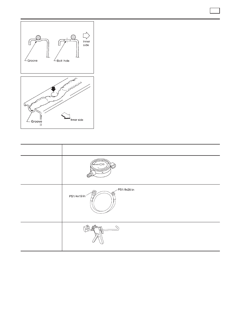
LIQUID GASKET APPLICATION PROCEDURE

NLLC0039

1.

Use a scraper to remove all traces of old liquid gasket from
mating surfaces and grooves. Also, completely clean any oil
from these areas.

2.

Apply a continuous bead of liquid gasket to mating surfaces.
(Use Genuine Liquid Gasket or equivalent.)

I

For oil pan, be sure liquid gasket diameter is 4.0 to 5.0 mm
(0.157 to 0.197 in).

I

For areas except oil pan, be sure liquid gasket diameter is 2.0
to 3.0 mm (0.079 to 0.118 in).

3.

Apply liquid gasket around the inner side of bolt holes (unless
otherwise specified).

4.

Assembly should be done within 5 minutes after coating.

5.

Wait at least 30 minutes before refilling engine oil and engine
coolant.

Preparation

SPECIAL SERVICE TOOLS

NLLC0040

Tool number
Tool name

Description

ST25051001
Oil pressure gauge

NT050

ST25052000
Hose

NT559

Adapting oil pressure gauge to upper oil pan

WS39930000
Tube presser

NT052

Pressing the tube of liquid gasket

ENGINE LUBRICATION SYSTEM

YD

Precautions

LC-22

Lubrication Circuit

NLLC0041

JLC315B

GI

MA

EM

EC

FE

CL

MT

AT

AX

SU

BR

ST

RS

BT

HA

SC

EL

IDX

ENGINE LUBRICATION SYSTEM

YD

Lubrication Circuit

LC-23

SLC283B

Oil Pressure Check

NLLC0042

JLC284B

SLC926-A

WARNING:

I

Be careful not to burn yourself, as the engine and oil may
be hot.

I

Oil pressure check should be done in “Neutral position”.

1.

Check oil level.

2.

Remove exhaust front tube.

3.

Remove oil pressure switch.

4.

Install pressure gauge.

5.

Install exhaust front tube.

6.

Start engine and warm it up to normal operating temperature.

7.

Check oil pressure with engine running under no-load.

Engine speed

rpm

Approximate discharge pressure

kPa (bar, kg/cm

2

, psi)

Idle speed

More than 140 (1.40, 1.43, 20.3)

2,000

More than 270 (2.69, 2.75, 39.1)

4,000

More than 430 (4.29, 4.38, 62.3)

If difference is extreme, check oil passage and oil pump
for oil leaks.

8.

After the inspections, install the oil pressure switch as follows.

a.

Remove the old sealant adhering to the switch and engine.

b.

Apply Genuine Liquid Gasket or equivalent to the thread and
tighten.

: 13 - 17 N·m (1.25 - 1.75 kg-m, 9 - 12 ft-lb)

Oil Pump

REMOVAL AND INSTALLATION

NLLC0043

I

When installing oil pump, apply engine oil to rotors.

Refer to EM-176, “Primary Timing Chain” for removal.
Reinstall all parts in the reverse order of removal.

ENGINE LUBRICATION SYSTEM

YD

Oil Pressure Check

LC-24

DISASSEMBLY AND ASSEMBLY

NLLC0044

JLC285B

JLC286B

JLC355B

OIL PUMP INSPECTION

NLLC0045

I

Install the inner rotor and outer rotor with the punched
marks on the pump cover side.

Using a feeler gauge, straightedge and micrometers, check the
following clearances:

Unit: mm (in)

Body to outer rotor radial clearance 1

0.114 - 0.260 (0.0045 - 0.0102)

Inner rotor to outer rotor tip clearance
2

Below 0.18 (0.0071)

Body to inner rotor axial clearance 3

0.050 - 0.090 (0.0020 - 0.0035)

Body to outer rotor axial clearance 4

0.030 - 0.190 (0.0012 - 0.0075)

Inner rotor to brazed portion of hous-
ing clearance 5

0.045 - 0.091 (0.0018 - 0.0036)

I

If the tip clearance (2) exceeds the limit, replace rotor set.

I

If body to rotor clearances (1, 3, 4, 5) exceed the limit,
replace oil pump body assembly.

GI

MA

EM

EC

FE

CL

MT

AT

AX

SU

BR

ST

RS

BT

HA

SC

EL

IDX

ENGINE LUBRICATION SYSTEM

YD

Oil Pump (Cont’d)

LC-25


Content   ..  898  899  900  901   ..