Nissan Almera Tino V10. Manual - part 888


  Index      Nissan     Nissan Almera Tino V10 - Service Manual (2003 year)


Search            


Content   ..  886  887  888  889   ..


Nissan Almera Tino V10. Manual - part 888


EM-208

[YD]

CYLINDER BLOCK

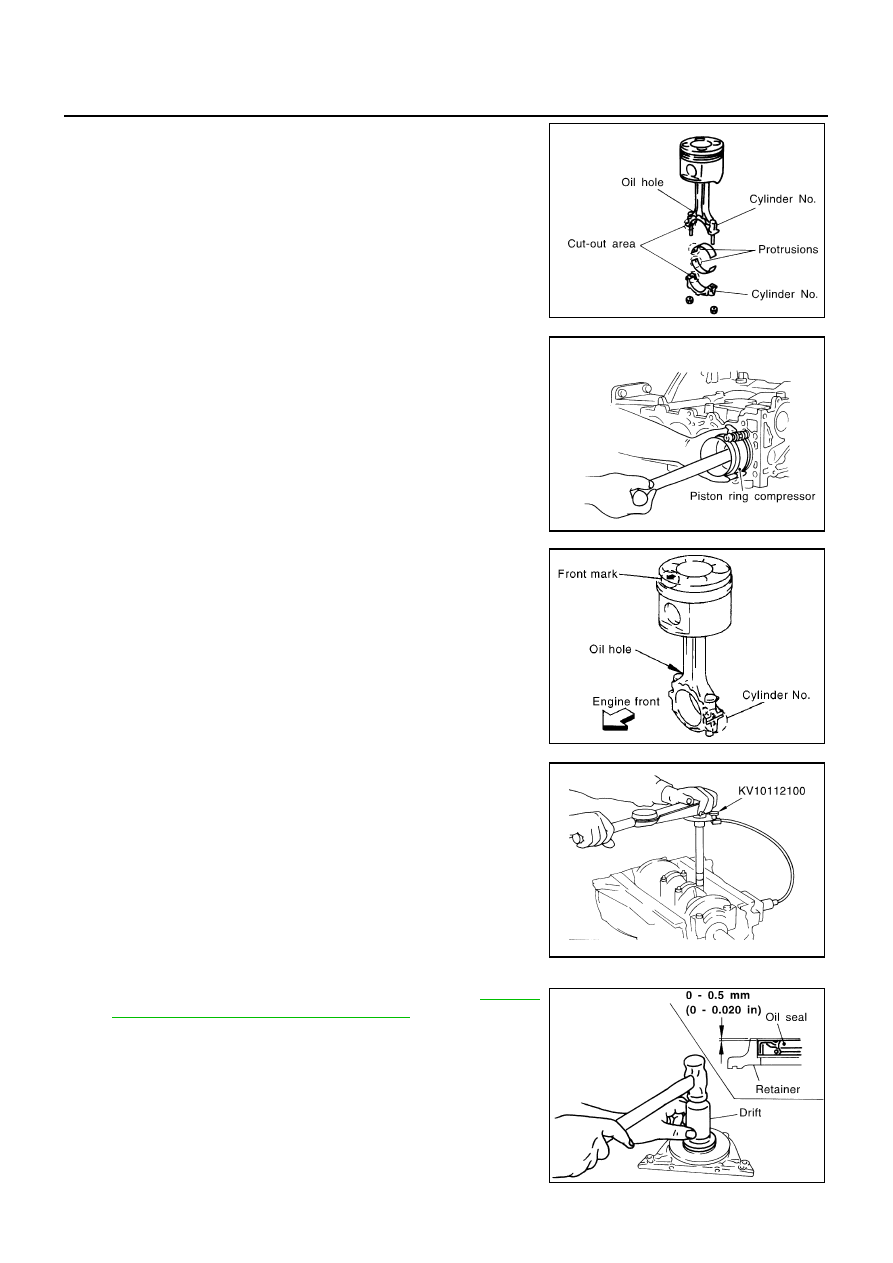
12. Install connecting rod bearings to connecting rods and caps.

While installing connecting rod bearings, apply engine oil to
bearing surfaces (inside). Do not apply oil to rear surfaces,
but clean them completely.

Align stoppers on connecting rod bearings with connecting
rod stopper notches to install connecting rod bearings.

13. Install piston and connecting rod assembly to crankshaft.

Move crankshaft pin to be assembled to BDC.

Align cylinder position with cylinder No. on connecting rod to
install piston and connecting rod assembly.

Using piston ring compressor, install piston and connecting
rod assembly with front mark on piston crown facing toward
the front side of engine.

CAUTION:

When installing piston and connecting rod assembly, pre-
vent the big end of connecting rod from interfering with oil
jet.

14. Install connecting rod caps and mounting nuts.

Align cylinder No. stamped on connecting rod with that on cap
to install connecting rod cap.

Make sure that the front mark on connecting rod cap faces
towards the front of the engine.

15. Tighten connecting rod nuts according to the following proce-

dure:

a.

Apply engine oil on bolt threads and seat surface of nuts.

b.

Tighten to 29 to 30 N·m (2.9 to 3.1 kg-m, 21 to 22 ft-lb).

c.

Loosen completely to 0 N·m (0 kg-m, 0 in-lb).

d.

Tighten to 19 to 20 N·m (1.9 to 2.1 kg-m, 14 to 15 ft-lb).

e.

Tighten 120

°

to 125

°

[target: 120

°

]. (angular tightening)

Always use either an angle wrench (SST) or protractor
during angular tightening. Avoid tightening based on
visual checks alone.

After tightening nuts, check that crankshaft rotates smoothly.

Check connecting rod side clearance. Refer to

EM-214,

"CONNECTING ROD SIDE CLEARANCE"

.

16. Force fit rear oil seal into rear oil seal retainer.

Using a drift [105 mm (4.13 in) dia.], force fit so that the
dimension is as specified in the figure.

Avoid inclined fitting. Force fit perpendicularly.

Do not touch lips of oil seal. Make sure seal surfaces are
free foreign materials.

JEM229G

JEM230G

MBIA0024E

JEM231G

JEM232G

CYLINDER BLOCK

EM-209

[YD]

C

D

E

F

G

H

I

J

K

L

M

A

EM

17. Install rear oil seal and retainer assembly.

Apply a continuous bead of liquid gasket to rear oil seal and
retainer assembly as shown in the figure.

18. Press fit pilot bushing into flywheel.

Using drift with outer diameter of 19 mm (0.75 in), press fit
pilot bushing until it stops.

19. Install fuel supply pump bracket.

Align the bracket with the dowel pins on the block to install.

The two bolts used for dowel pins have a longer shanks than
the other two.

20. Install parts to the engine in the reverse order of disassembly.

21. Remove engine from engine stand in the reverse order of

assembly.

22. Install flywheel.

When installing flywheel to crankshaft, be sure to correctly
align crankshaft side dowel pin and flywheel side dowel pin-
hole.

JEM233G

JEM234G

PBIC0762E

PBIC0952E

EM-210

[YD]

CYLINDER BLOCK

There is a mating mark on the clutch cover side, Refer it dur-
ing installation.

Holding ring gear with ring stopper (SST), tighten securing bolts with TORX bit (size: Q6T55 E9, Com-
mercial Service Tool).

Tighten bolts uniformly in a crisscross manner.

How to Select Piston and Bearing

EBS00QFY

DESCRIPTION

The identification grade stamped on each part is the grade for the dimension measured in new condition.
This grade cannot apply to reused parts.

For reused or repaired parts, measure the dimension accurately. Determine the grade by comparing the
measurement with the values of each selection table.

For details of the measurement method of each part, the reuse standards and the selection method of the
selective fitting parts, refer to the text.

HOW TO SELECT PISTON
When Using New Cylinder Block

1.

Identify the cylinder bore grade (No. 1, 2, or 3) on LH surface at
the rear of cylinder block.

2.

Select the piston of the same grade.

The part No. of piston is specified together with the piston pin as
an assembly.

PBIC0981E

Selection points

Selection parts

Selection items

Selection methods

Between cylinder block to
crankshaft

Main bearing

Main bearing grade (bearing
thickness)

Determined by match of cylin-
der block bearing housing
grade (inner diameter of hous-
ing) and crankshaft journal
grade (outer diameter of jour-
nal)

Between crankshaft to connect-
ing rod

Connecting rod bearing

Connecting rod bearing grade
(bearing thickness)

Combining service grades for
connecting rod bearing and
crankshaft pin outer diameter
determine connecting rod bear-
ing selection.

Between cylinder block to pis-
ton

Piston and piston pin assembly
The piston is available together
with piston pin as an assembly.

Piston grade (piston outer
diameter)

Piston grade = cylinder bore
grade (inner diameter of bore)

JEM208G

CYLINDER BLOCK

EM-211

[YD]

C

D

E

F

G

H

I

J

K

L

M

A

EM

When Re-using an Old Cylinder Block

1.

Measure cylinder block bore inner diameter.

2.

Referring to “Cylinder block bore inner diameter” in “Piston
Selection Table”, determine the bore grade.

3.

Select the piston of the same grade.

Piston Selection Table

Unit: mm (in)

HOW TO SELECT CONNECTING ROD BEARING
When Using a New Crankshaft and Connecting Rod

1.

Identify the pin diameter grade (No. 0, 1, or 2) on front surface of
crankshaft.

2.

Select the connecting rod bearings of the same grade.

There is no grading for the inner diameter of the big end of the
connecting rod.

When Re-using the Removed Crankshaft and Connecting Rod

1.

Measure the inner diameter of the big end of the connecting rod and make sure it is within the specified
range.

2.

Measure the outer diameter of the crankshaft pin.

3.

Determine the crankshaft pin grade by comparing the measurement with the values under the column
“Crankshaft pin outer diameter” of the table below.

4.

Choose the bearings of the same grade.

Selection Table of connecting Rod Bearing

Unit: mm (in)

MBIA0025E

Grade (punched)

1

2

3

Cylinder bore
inner diameter

86.000 - 86.010(3.3858 - 3.3862)

86.010 - 86.020(3.3862 - 3.3866)

86.020 - 86.030(3.3866 - 3.3870)

Piston outer
diameter

85.928 - 85.942(3.3830 - 3.3835)

85.938 - 85.952(3.3834 - 3.3839)

85.948 - 85.962(3.3838 - 3.3843)

JEM215G

Connecting rod big end inner diameter

55.000 - 55.013 (2.1654 - 2.1659)

Crankshaft pin outer diameter

Grade (punched)

0 (no punching)

51.968 - 51.974

(2.0460 - 2.0462)

0

Bearing grade No.

Bearing thickness

Oil clearance

Identification color

STD 0

1.492 - 1.496

(0.0587 - 0.0589)

0.031 - 0.061

(0.0012 - 0.0024)

Black


Content   ..  886  887  888  889   ..