Nissan Almera Tino V10. Manual - part 886


  Index      Nissan     Nissan Almera Tino V10 - Service Manual (2003 year)


Search            


Content   ..  884  885  886  887   ..


Nissan Almera Tino V10. Manual - part 886


EM-200

[YD]

ENGINE ASSEMBLY

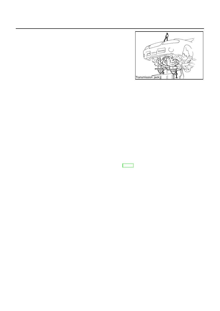
23. Carefully lower transmission jacks in accordance with the lower-

ing pace of the hoist, and remove engine and transaxle assem-
bly from vehicle.

CAUTION:

While working, check that no parts of engine assembly
interfere with adjacent parts on the vehicle.

While working, make sure that parts requiring disconnec-
tion are not left connected, and that no parts interfere
with vehicle.

to prevent vehicle from falling down, perform operation
carefully so that the center of gravity of the vehicle will
not shift.

24. Remove center member.

CAUTION:

Before starting removal operation, first place the assembly on a level surface and securely sup-
port the bottom surface with wood blocks Using a hoist, lift engine slingers and make sure the
assembly is stable.

25. Separate engine and transaxle.

INSTALLATION

Install in the reverse order of removal.

Do not allow oil to get on mounting insulator. Be careful not to damage mounting insulator.

When installation directions are specified, install parts according to the direction marks on them referring
to components illustration.

Make sure that each mounting insulator is seated properly, and tighten mounting bolts and nuts.

INSPECTION AFTER INSTALLATION

Before starting engine check the levels of coolant, lubrications and working oils. If less than required
quantity, fill to the specified level.

Before starting engine, bleed air from fuel piping. Refer to FE-18, “Bleeding Fuel Filter”.

Run engine to check for unusual noise and vibration.

Warm up engine thoroughly to make sure there is no leakage of coolant, lubricants, working oil, fuel and
exhaust gas.

Bleed air from passages in pipes and tubes of applicable lines.

JEM190G

CYLINDER BLOCK

EM-201

[YD]

C

D

E

F

G

H

I

J

K

L

M

A

EM

CYLINDER BLOCK

PFP:11010

Disassembly and Assembly

EBS00QFX

MBIA0015E

EM-202

[YD]

CYLINDER BLOCK

CAUTION:

Apply new engine oil to parts marked in illustration before installation.

DISASSEMBLY

1.

Remove engine assembly from the vehicle, then separate engine and transaxle. Refer to

EM-197,

"ENGINE ASSEMBLY"

.

2.

Remove clutch cover and disk. Refer to CL-22 (5MT),

CL-16

(6MT).

3.

Install engine to engine stand as follows.

a.

Remove flywheel.

b.

Secure ring gear with ring gear stopper, then loosen mounting
bolts with TORX bit (size: Q6T55 E9, Commercial Service Tools)
and remove them. As an alternative method hold the crankshaft
pulley with a pulley holder (SST) to remove the flywheel.

CAUTION:

Do not disassemble flywheel.

c.

Install engine sub-attachment to the rear side of cylinder block.

Align knock pins on cylinder block with pin holes on attach-
ment to install.

NOTE:
Installation bolts are part of engine sub-attachment.

d.

Install engine attachment.

NOTE:
Use commercially available M12 (0.47 in) mounting bolts and
nuts (4 sets) with strength grade of 9T (minimum).

1.

Rear oil seal retainer

2.

Oil pressure switch

3.

Coppet washer

4.

Oil jet relief valve

5.

Cylinder block

6.

Top ring

7.

Second ring

8.

Oil ring

9.

Oil jet

10.

Piston pin

11.

Snap ring

12.

Piston

13.

Main bearing

14.

Thrust bearing

15.

Connecting rod

16.

Key

17.

Connecting rod bearing

18.

Connecting rod cap

19.

Connecting rod nut

20.

Main bearing

21.

Crankshaft

22.

Main bearing cap

23.

Pilot bush

24.

Flywheel

25.

Drain plug

26.

Rear oil seal

SBIA0199E

JEM192G

CYLINDER BLOCK

EM-203

[YD]

C

D

E

F

G

H

I

J

K

L

M

A

EM

e.

Hoist engine and install it to the engine stand.

NOTE:
It is possible to set engine sub-attachment and engine attach-
ment to engine stand at first, then install engine later.

Commercial engine stand can be used.

NOTE:
The figure shows an example of general-purpose engine stand
that can hold mating surface of transmission with drive plate and
rear plate removed.

4.

Drain engine oil and coolant from inside engine.

5.

Remove the following parts and related parts. (Only major parts are listed.)

Intake manifold (Refer to

EM-123, "Removal and Installation"

.)

Exhaust manifold and turbocharger (Refer to

EM-128, "Removal and Installation"

.)

Rocker cover (Refer to

EM-160, "Removal and Installation"

).

Injection tube and fuel injector (Refer to

EM-147, "Removal and Installation"

.)

Oil pan and oil strainer (Refer to

EM-137, "Removal and Installation"

.)

Water pump (Refer to LC-35, “Water Pump”.)

Thermostat and water piping (Refer to LC-37, “Thermostat”.)

Vacuum pump (Refer to

EM-143, "Removal and Installation"

.)

Secondary timing chain (Refer to

EM-171, "Removal and Installation"

)

Primary timing chain (Refer to

EM-176, "Removal and Installation"

.)

Fuel pump (Refer to

EM-150, "Removal and Installation"

.)

Camshaft (Refer to

EM-162, "Removal and Installation"

.)

Cylinder head (Refer to

EM-187, "Removal and Installation"

.)

Oil cooler (Refer to LC-30, “Oil Cooler”.)

Accessory, accessory bracket and mount brackets

6.

Remove fuel supply pump bracket.

JEM193G

PBIC0085E


Content   ..  884  885  886  887   ..