Nissan Almera Tino V10. Manual - part 884
EM-192
[YD]
CYLINDER HEAD
5.
Remove valve oil seals using valve oil seal puller.
6.
Remove valve spring seats.
7.
Before removing valve spring seats, perform valve seat contact
check. Refer to
.
8.
Before removing valve guides, perform valve guide clearance
check. Refer to
EM-193, "Valve Guide Clearance"
.
ASSEMBLY
1.
Install valve guides. Refer to
EM-193, "Valve Guide Replacement"
.
2.
Install valve seats. Refer to
EM-194, "Valve Seat Replacement"
.
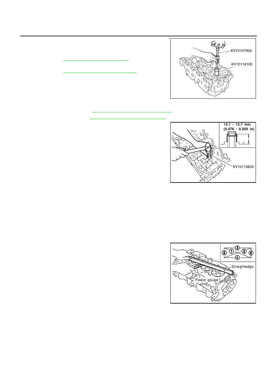
3.
Using valve oil seal drift, install valve oil seals referring to the
dimension shown in the figure.
4.
Install valve spring seats.
5.
Install valves.
●
Install the valves with bigger outer diameter to intake valve
side.
●
Note that valve layout here is different from that of conven-
tional engine.
6.
Install valve spring.
7.
Install valve spring retainers.
8.
Using valve spring compressor, compress valve springs.
Then install valve collets using magnetic hand.
●
After installing valve collets, tap the stem end using a plastic hammer, and check the installation status.
9.
Install valve lifters and adjusting shims to the same positions as before.
INSPECTION AFTER DISASSEMBLY
Cylinder Head Distortion
Using straightedge and feeler gauge, check the bottom of the cylin-
der head for distortion.
JEM153G
JEM165G
Limit
: 0.04 mm (0.0016 in)
SEM496G