Nissan Almera Tino V10. Manual - part 882


  Index      Nissan     Nissan Almera Tino V10 - Service Manual (2003 year)


Search            


Content   ..  880  881  882  883   ..


Nissan Almera Tino V10. Manual - part 882


EM-184

[YD]

PRIMARY TIMING CHAIN

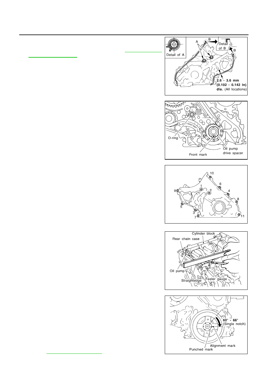
13. Install oil pump housing.

a.

Apply a continuous bead of Genuine Liquid Gasket or equiva-
lent on locations shown in the figure. Refer to

EM-110, "Precau-

tions for Liquid Gasket"

.

A: Leave the start and end areas of the bead slightly protruding
from the surface.
B: Apply liquid gasket along upper end surface of oil pump hous-
ing.

b.

Install oil pump drive spacer to crankshaft.

Install with the front mark (punched mark) facing the front of
the engine.

c.

Install O-ring into the groove of rear chain case.

d.

Install oil pump housing.

When installing, align the inner rotor in the direction of the two
facing flats of the oil pump drive spacer.

When installing, align the dowel pin with the pin hole.

e.

Tighten fixing bolts in the numerical order shown in the figure.

f.

After tightening all the bolts, re-tighten in the same order.

14. Check gaps on upper oil pan mounting surface.

Using straightedge and feeler gauge, measure gaps between
the locations of the following parts:

If the measured value is out of the above range, install again.

15. Install crankshaft pulley.

a.

Install crankshaft pulley to crankshaft.

b.

Hold crankshaft pulley with the pulley holder (SST).

c.

Tighten bolt to 20 to 29 N·m (2.0 to 3.0 kg-m,15 to 21 ft-lb).

d.

Put an alignment mark on crankshaft pulley that aligns with one
of the punched marks on the bolt.

e.

Tighten fixing bolt another 60

°

- 66

°

[target: 60

°

(turn by one

notch)].

16. Install secondary timing chain and the associated parts.

Refer to

EM-174, "INSTALLATION"

.

JEM144G

JEM145G

JEM133G

Oil pump housing and rear chain case:

Standard

: – 0.14 to 0.14 mm (– 0.0055 to 0.0055 in)

Rear chain case and cylinder block:

Standard

: – 0.25 to 0.13 mm (– 0.0098 to 0.0051 in)

JEM146G

JEM147G

PRIMARY TIMING CHAIN

EM-185

[YD]

C

D

E

F

G

H

I

J

K

L

M

A

EM

17. Install in the reverse order of removal hereafter.

EM-186

[YD]

CYLINDER HEAD

CYLINDER HEAD

PFP:11041

On-Vehicle Service

EBS00QFT

CHECKING COMPRESSION PRESSURE

1.

Warm up engine thoroughly. Then, stop it.

2.

Using CONSULT-II, make sure no error codes are indicated for self-diagnosis items. Refer to

EC-971,

"Basic Inspection"

.

Do not disconnect CONSULT-II until the end of this operation; it will be used to check engine rpm and
for error detection at the end of this operation.

3.

Disconnect the negative battery cable.

4.

To prevent fuel from being injected during inspection, remove
fuse [ECCS (20A)] from fuse box on the left side of engine com-
partment.

5.

Remove glow plugs from all the cylinders. Refer to

EM-142,

"Removal and Installation"

.

CAUTION:

Before removal, clean the surrounding area to prevent
entry of any foreign materials into the engine.

Carefully remove glow plugs to prevent any damage or
breakage.

Handle with care to avoid applying any shock to glow
plugs.

6.

Install adapter to installation holes of glow plugs and connect
compression gauge for diesel engine.

7.

Connect battery negative terminal.

8.

Set the ignition switch to “START” and crank. When gauge
pointer stabilizes, read compression pressure and engine rpm.
Repeat the above steps for each cylinder.

Always use a fully-charged battery to obtain specified engine
speed.

Unit: kPa (bar, kg/cm

2

, psi)/rpm

When engine rpm is out of the specified range, check the specific gravity of battery liquid. Measure
again under corrected conditions.

If engine rpm exceeds the limit, check valve clearance and combustion chamber components (valves,
valve seats, cylinder head gaskets, piston rings, pistons, cylinder bores, cylinder block upper and lower
surfaces) and measure again.

If compression pressure is low in some cylinders, apply engine oil from glow plug installation hole. Then
check pressure again.

If compression pressure becomes normal after applying oil, piston ring may be worn or damaged.
Check piston ring for malfunction. If any, replace piston ring.

If compression pressure is still low after applying oil, valve may be malfunctioning. Check valve for mal-
function. If contact malfunction is found, replace valve or valve seat.

If compression pressure in adjacent two cylinders is low after applying oil, pressure may be leaking
from gasket. In this case, replace cylinder head gasket.

9.

Complete this operation as follows.

a.

Turn the ignition switch to “OFF”.

b.

Disconnect negative battery cable.

MBIA0019E

: 18 - 21 N·m (1.8 - 2.2 kg-m, 13 - 15 ft-lb)

Standard

Minimum

Difference limit between

cylinders

2,991 (29.9, 30.5, 2,434)/

200

2,452 (24.52, 25.0, 356)/

200

490 (4.90, 5.0, 71)/200

SEM112G

CYLINDER HEAD

EM-187

[YD]

C

D

E

F

G

H

I

J

K

L

M

A

EM

c.

Install glow plug and install all the parts removed in step 4.

d.

Install fuse [ECCS (20A)].

e.

Connect negative battery cable.

f.

Using CONSULT-II make sure no error code is indicated for items of self-diagnosis.

Removal and Installation

EBS00QFU

CAUTION:

Apply new engine oil to parts marked in illustration before installation.

REMOVAL

1.

Drain engine coolant. Refer to LC-40, “Changing Engine Coolant”.

2.

Remove the following parts.

Rocker cover (Refer to

EM-160, "Removal and Installation"

.)

Air cleaner and air duct (Refer to

EM-119, "Removal and Installation"

.)

Vacuum pump (Refer to

EM-143, "Removal and Installation"

.)

Injection tube, spill tube and fuel injector (Refer to

EM-147, "Removal and Installation"

.)

Intake manifold (Refer to

EM-123, "Removal and Installation"

.)

Exhaust manifold and turbocharger (Refer to

EM-128, "Removal and Installation"

.)

Secondary timing chain (Refer to

EM-171, "Removal and Installation"

.)

Camshaft (Refer to

EM-162, "Removal and Installation"

.)

PBIC0946E

1.

Glow plug

2.

Cylinder head assembly

3.

Cylinder head bolt

4.

Gasket

5.

Engine coolant temperature sensor

6.

Gasket

7.

Water outlet

8.

Glow plate


Content   ..  880  881  882  883   ..