Nissan Almera Tino V10. Manual - part 889
EM-212
[YD]
CYLINDER BLOCK
Under Size Bearing Usage
●
If bearing clearance is out of specifications for connecting rod bearings in standard size, use under size
bearings.
●
When using under size bearings, measure bearing inner diameter with bearing installed, and grind crank-
shaft pins to adjust clearance to specification.
Connecting Rod Bearing Under Size list
Unit: mm (in)
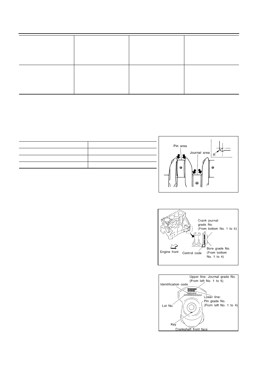
CAUTION:
When grinding the crankshaft journal to use an under size bear-
ing, avoid damaging the fillet R.
HOW TO SELECT MAIN BEARING
When Using a New Cylinder Block and Crankshaft
1.
Identify the bearing housing grade (No. 0, 1, or 2) on LH surface
at the rear of the cylinder block, and locate the applicable grade
on the “Grade” row in the table below.
2.
Identify the journal grade (No. 0, 1, or 2) on the front surface of
the crankshaft, and locate the applicable grade under the
“Grade” column on the table.
3.
The main bearing to be used (STD 0 to STD 4) can be located
in the cell where the row and column cross.
When Re-using Removed Cylinder Block and Crankshaft
1.
Measure the inner diameter of cylinder block main bearing hous-
ing.
2.
Locate the applicable cell where the measurement falls, on
“Inner diameter of cylinder block main bearing housing” row on
the table.
3.
Measure the outer diameter of the crankshaft journal.
4.
Locate the applicable cell where the measurement falls, under
“Crankshaft journal outer diameter” column on the table.
5.
The main bearing to be used (STD 0 to STD 4) can be located in
the cell where the row and column cross.
51.961 - 51.968
(2.0457 - 2.0460)
1
●
Bearing grade No.
●
Bearing thickness
●
Oil clearance
●
Identification color
STD 1
1.496 - 1.500
(0.0589 - 0.0591)
0.031 - 0.061
(0.0012 - 0.0024)
Brown
51.954 - 51.961
(2.0454 - 2.0457)
2
●
Bearing grade No.
●
Bearing thickness
●
Oil clearance
●
Identification color
STD 2
1.500 - 1.504
(0.0591 - 0.0592)
0.031 - 0.061
(0.0012 - 0.0024)
Green
Size
Thickness
US 0.08 (0.0031)
1.536 - 1.540 (0.0605 - 0.0606)
US 0.12 (0.0047)
1.556 - 1.560 (0.0613 - 0.0614)
US 0.25 (0.0098)
1.621 - 1.625 (0.0638 - 0.0640)
Standard dimension R
: 1.5 - 1.7 mm (0.0591 - 0.0669 in)
JEM216G
JEM208G
JEM215G