Nissan Almera Tino V10. Manual - part 783


  Index      Nissan     Nissan Almera Tino V10 - Service Manual (2003 year)


Search            


Content   ..  781  782  783  784   ..


Nissan Almera Tino V10. Manual - part 783


2

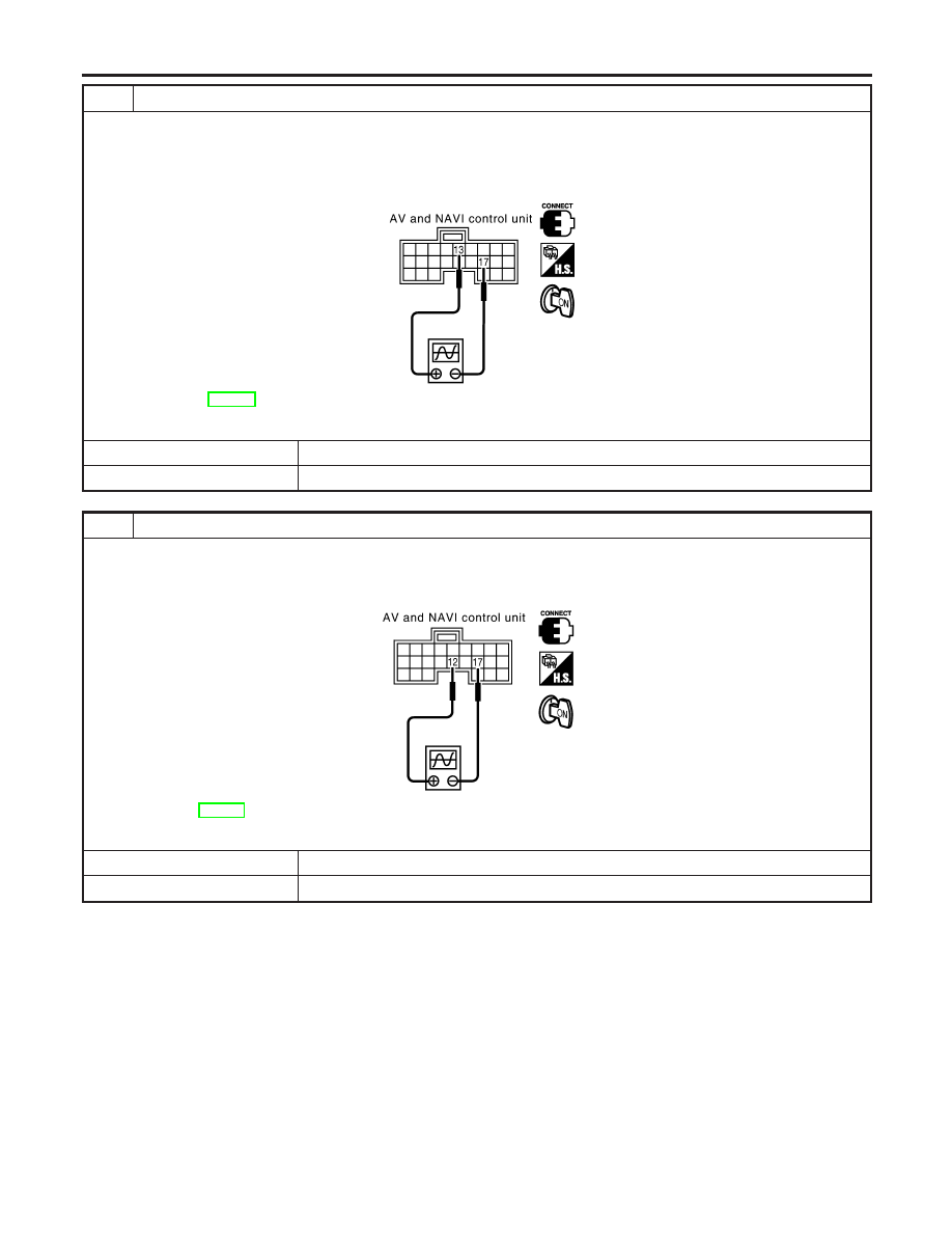
HORIZONTAL SYNCHRONIZATION SIGNAL CHECK

1. Connect AV and NAVI control unit connector and Display connector.
2. Turn the ignition switch ON.
3. Check voltage signal between AV and NAVI control unit connector terminals 13 (BR) and 17 with oscilloscope or CON-

SULT-ll.

YEL383E

13 (BR)-17: EL-400, “Terminals and Reference Value for AV and NAVI Control Unit”

OK or NG

OK

©

GO TO 3.

NG

©

Replace the display unit.

3

RGB AREA SIGNAL CHECK

1. Press “INFO” switch.
2. Check voltage signal between AV and NAVI control unit connector terminals 12 (R) and 17with oscilloscope or CON-

SULT-ll.

YEL384E

12 (R)-17: EL-400, “Terminals and Reference Value for AV and NAVI Control Unit”

OK or NG

OK

©

Replace the display unit.

NG

©

Replace AV and NAVI control unit.

NAVIGATION SYSTEM

Trouble Diagnoses (Cont’d)

EL-428

NO SCREENS APPEAR

=NLEL0687S09

1

CHECK SYMPTOM

Check possibility to operate air conditioning and audio unit by multifunction switch.

OK or NG

OK

©

GO TO 2.

NG

©

EL-447, “System Does Not Start”.

2

DISPLAY UNIT POWER SYSTEM HARNESS CHECK

Check voltage between Display and ground. EL-419 , “Check Power Supply and Ground Circuit for Display”.

OK or NG

OK

©

Replace the display unit.

NG

©

Open or short in display unit power system harness.

GI

MA

EM

LC

EC

FE

CL

MT

AT

AX

SU

BR

ST

RS

BT

HA

SC

IDX

NAVIGATION SYSTEM

Trouble Diagnoses (Cont’d)

EL-429

COLOR OF RGB IMAGE IS NOT PROPER

=NLEL0687S10

1

COLOR BAR DIAGNOSIS CHECK

Check color tone by “SCREEN ADJUSTMENT” of CONFIRMATION/ADJUSTMENT function.

OK or NG

OK

©

INSPECTION END.

NG

©

GO TO 2.

2

HARNESS CHECK-1

1. Turn the ignition switch OFF.
2. Disconnect AV and NAVI control unit connector and Display connector.
3. Check continuity between AV and NAVI control unit and Display.
4. Check continuity between AV and NAVI control unit and ground.

I

When the screen looks bluish

YEL385E

MTBL1731

MTBL1732

OK or NG

OK

©

GO TO 3.

NG

©

I

Repair harness.

I

Check connector housings for disconnected or loose terminals.

NAVIGATION SYSTEM

Trouble Diagnoses (Cont’d)

EL-430

3

HARNESS CHECK-2

1. Check continuity between AV and NAVI control unit and ground.

I

When the screen looks reddish

YEL386E

MTBL1733

MTBL1734

OK or NG

OK

©

GO TO 4.

NG

©

I

Repair harness.

I

Check connector housings for disconnected or loose terminals.

GI

MA

EM

LC

EC

FE

CL

MT

AT

AX

SU

BR

ST

RS

BT

HA

SC

IDX

NAVIGATION SYSTEM

Trouble Diagnoses (Cont’d)

EL-431


Content   ..  781  782  783  784   ..