Nissan Almera Tino V10. Manual - part 734


  Index      Nissan     Nissan Almera Tino V10 - Service Manual (2003 year)


Search            


Content   ..  732  733  734  735   ..


Nissan Almera Tino V10. Manual - part 734


POWER SUPPLY AND GROUND CIRCUIT CHECK FOR
MULTIFUNCTION SWITCH

=NLEL0689S02

1

CHECK FUSES

Check the fuse below.

MTBL1653

OK or NG

OK

©

GO TO 2.

NG

©

If fuse is blown, be sure to eliminate cause of malfunction before installing new fuse.

2

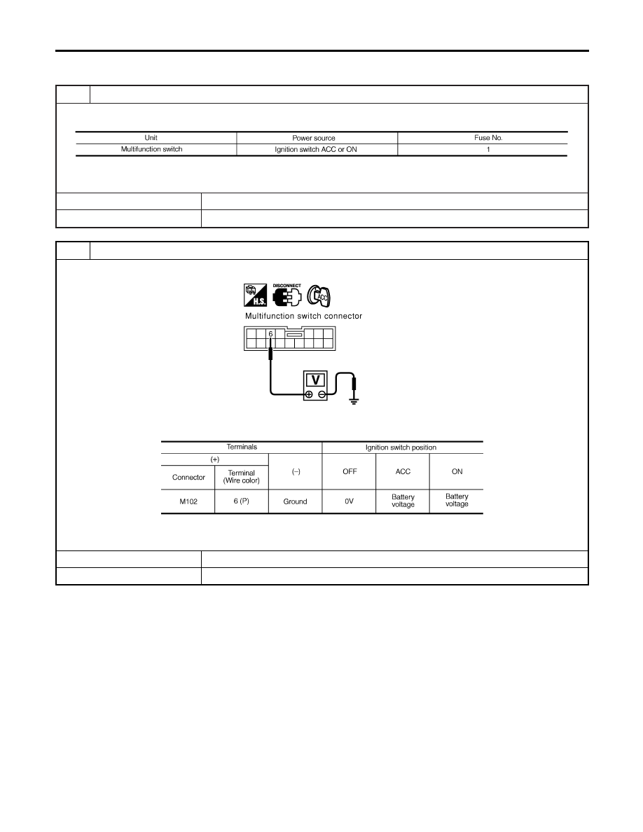
POWER SUPPLY CIRCUIT CHECK

1. Disconnect multifunction switch connector.

MKIB0103E

2. Check voltage between multifunction switch and ground.

MTBL1654

OK or NG

OK

©

GO TO 3.

NG

©

Check harness for open or short between multifunction switch and fuse.

LCD (LIQUID CRYSTAL DISPLAY)

Trouble Diagnoses (Cont’d)

EL-232

3

GROUND CIRCUIT CHECK

Check continuity between multifunction switch harness connector M102 terminal 1 (B) and ground.

MKIB0104E

Continuity should exist.

OK or NG

OK

©

INSPECTION END

NG

©

Check ground harness.

GI

MA

EM

LC

EC

FE

CL

MT

AT

AX

SU

BR

ST

RS

BT

HA

SC

IDX

LCD (LIQUID CRYSTAL DISPLAY)

Trouble Diagnoses (Cont’d)

EL-233

VEHICLE SPEED SIGNAL CHECK

=NLEL0689S03

1

HARNESS CHECK

1. Disconnect display unit connector and combination meter.
2. Check the following.

Continuity between display unit connector M96 terminal 11 (L/B) and combination meter connector M84 terminal 10
(L/B).

YEL404E

Continuity should exist.

Continuity between display unit connector M96 terminal 11 (L/B) and ground.

Continuity should not exist.

OK or NG

OK

©

GO TO 2.

NG

©

Replace harness or connector.

LCD (LIQUID CRYSTAL DISPLAY)

Trouble Diagnoses (Cont’d)

EL-234

2

VEHICLE SPEED SIGNAL CHECK

Connect combination meter connector and display unit connector.

With CONSULT-II

1. Lift up drive wheels.
2. Start engine and drive vehicle at more than 20 km/h (12 MPH).
3. Check signal between display unit connector M96 terminal 11 (L/B) and ground when rotating wheels with engine at

idle. (Use “SIMPLE OSCILLOSCOPE” in “SUB MODE” with CONSULT-II.)

YEL573E

11 - Ground: “Terminal and Reference Value for Display” EL-221

Without CONSULT-II

1. Lift up drive wheels.
2. Start engine and drive vehicle at more than 20 km/h (12 MPH).
3. Check voltage between display unit connector M96 terminal 11 (L/B) and ground when rotating wheels with engine at

idle.

MKIB0208E

Voltage: Approximately 0 - 5V

OK or NG

OK

©

Replace display unit.

NG

©

Check combination meter system. Refer to EL-107, “Combination Meter Self-Diagnoses”.

GI

MA

EM

LC

EC

FE

CL

MT

AT

AX

SU

BR

ST

RS

BT

HA

SC

IDX

LCD (LIQUID CRYSTAL DISPLAY)

Trouble Diagnoses (Cont’d)

EL-235


Content   ..  732  733  734  735   ..