Nissan Almera Tino V10. Manual - part 732


  Index      Nissan     Nissan Almera Tino V10 - Service Manual (2003 year)


Search            


Content   ..  730  731  732  733   ..


Nissan Almera Tino V10. Manual - part 732


On Board Self-diagnosis Function

NLEL0551

DESCRIPTION

=NLEL0551S01

I

Diagnosis function consists of the self-diagnosis mode per-
formed

automatically

and

the

CONFIRMATION/

ADJUSTMENT mode operated manually.

I

Self-diagnosis mode checks for connections between the units
constituting this system, analyzes each individual unit at the
same time, and displays the results on the LCD screen.

I

CONFIRMATION/ADJUSTMENT mode is used to perform
trouble diagnosis that require operation and judgment by an
operator (trouble that cannot be automatically judged by the
system), to check/change the set value.
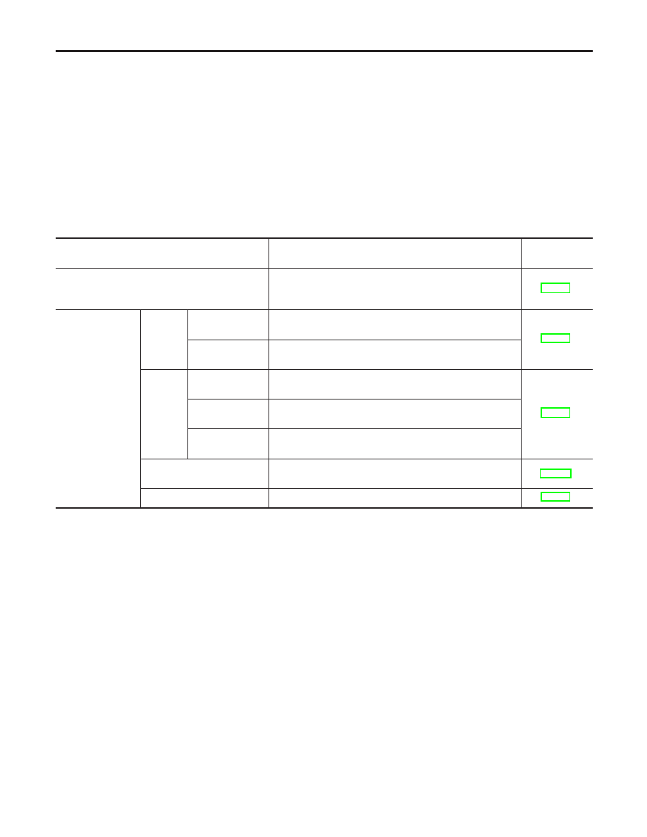
DIAGNOSIS ITEM

NLEL0551S02

Mode

Description

Reference

page

Self-diagnosis

I

Center control unit (display unit) diagnosis.

I

Analyzes connection between the display unit and each
unit, and operation of each unit.

EL-225

CONFIRMATION/
ADJUSTMENT

Display
Diagnosis

Display Color
Spectrum Bar

Color of display can be checked in this mode.

EL-228

Display Gradation
Bar

Gray gradation of display can be checked in this mode.

Vehicle
Signals

Vehicle Speed

Vehicle speed input signal to center control unit (display
unit), can be monitored in this mode.

EL-229

Light

Light input signal to center control unit (display unit), can be
monitored in this mode.

IGN

Ignition input signal to center control unit (display unit), can
be monitored in this mode.

Auto Climate Control

Trouble diagnosis for auto climate control unit (A/C auto
amp), can be checked in this mode.

ATC-41

Service

Service schedule can be changed in this mode

EL-229

LCD (LIQUID CRYSTAL DISPLAY)

On Board Self-diagnosis Function

EL-224

YEL832D

Self-diagnosis Mode

NLEL0552

OPERATION PROCEDURES

=NLEL0552S01

1.

Start the engine.

2.

Turn the audio system off.

3.

While pressing the “INFO” switch, turn the volume control dial
clockwise or counterclockwise for 30 clicks or more. (When the
self-diagnosis mode is started, a short beep will be heard.)

I

Shifting from current screen to previous screen is performed by
pressing “BACK” switch.

SKIA0381E

4.

The initial trouble diagnosis screen will be shown, and items
“SELF-DIAGNOSIS” and “CONFIRMATION/ADJUSTMENT”
will become selective.

SKIA0382E

5.

Perform self-diagnosis by selecting the “SELF-DIAGNOSIS”.

I

Self-diagnosis subdivision screen will be shown and the opera-
tion enters the self-diagnosis mode.

I

A bar graph shown below the self-diagnosis subdivision screen
indicates progress of the diagnosis.

SKIA0383E

6.

When the self-diagnosis completes, optional part confirmation
screen will be shown.

I

When connection of an optional part is judged malfunction, a
screen to check if the optional part is fitted on the vehicle or
not will be shown. When fitted, select the switch of the part on
the screen and press “END”. Then the “Self-diagnosis” screen
will be shown.

I

When the optional part is connected normally, the switch for
the part will not appear on the screen.

MKIB0135E

7.

On the “Self-diagnosis” screen, each unit name will be colored
according to the diagnosis result, as follows.

Green: No malfunctioning.
Yellow: Cannot be judged by self-diagnosis results.
Red: Unit is malfunctioning.

I

If several malfunctions are present in a unit, color of its switch
on the screen will be either red, yellow, or gray, determined by
the malfunction of the highest priority.

GI

MA

EM

LC

EC

FE

CL

MT

AT

AX

SU

BR

ST

RS

BT

HA

SC

IDX

LCD (LIQUID CRYSTAL DISPLAY)

Self-diagnosis Mode

EL-225

SKIA0385E

8.

Select a switch on the “Self-diagnosis” screen and comments
for the diagnosis results will be shown.

I

When the switch is green, the following comment will be
shown. “Self-diagnosis was successful. Further diagnosis and
adjustments are recommended. Follow the “confirmation and
adjustments” menu or refer to the service manual”.

I

When the switch is yellow, the following comment will be
shown. “Connection to the following unit is abnormal. See the
service manual for further details”.

I

When the switch is red, the following comment will be shown.
“Center Control Unit is abnormal”.

CAUTION:

If self-diagnosis cannot activated, refer to EL-242.

SELF-DIAGNOSIS RESULT

NLEL0552S02

Quick reference table
1.

Select an applicable diagnosis No. in the diagnosis result quick
reference table.

2.

Find estimated malfunctioning system in the diagnosis No.
table and perform check by referring to the AV communication
line circuit diagram.

3.

Turn the ignition switch to OFF and perform self-diagnosis
again.

Screen switch

Diagnosis No.

Switch color

Center control

unit *

Multifunction switch

Audio unit

CD auto changer

Red

×

1

Yellow

×

×

2

×

×

×

3

×

×

4

×

×

×

×

5

*: Center control unit = Display unit

CAUTION:

When an error is in the AV communication line, it cannot be
detected on the screen because self-diagnosis is inoperative.
SELF-DIAGNOSIS CODES

Diagnosis No.

Possible cause

Reference page

1

Display unit malfunction.

2

Multifunction switch power supply and ground circuit.

EL-232

3

Audio unit power supply and ground circuit. AV communication line between multi-
function switch and the display unit. Audio unit internal communication circuit.

EL-210

4

CD auto changer power supply and ground circuit. AV communication line between
CD auto changer and audio unit.

EL-210

5

AV communication line circuit malfunction.

EL-242

LCD (LIQUID CRYSTAL DISPLAY)

Self-diagnosis Mode (Cont’d)

EL-226

YEL832D

Confirmation/Adjustment Mode

=NLEL0553

OPERATION PROCEDURE

NLEL0553S01

1.

Start the engine.

2.

Turn the audio system off.

3.

While pressing the “INFO” switch, turn the volume control dial
clockwise or counterclockwise for 30 clicks or more. (When the
self-diagnosis mode is started, a short beep will be heard.)

I

Shifting from current screen to previous screen is performed by
pressing “BACK” switch.

SKIA0381E

4.

The initial trouble diagnosis screen will be shown, and items
“SELF-DIAGNOSIS” and “CONFIRMATION/ADJUSTMENT”
will become selective.

MKIB0137E

5.

When “CONFIRMATION/ADJUSTMENT” is selected on the
initial trouble diagnosis screen, the operation will enter the
CONFIRMATION/ADJUSTMENT mode. In this mode, check
and adjustment of each item will become possible.

6.

Select each switch on “CONFIRMATION/ADJUSTMENT”
screen to display the relevant diagnosis screen.

GI

MA

EM

LC

EC

FE

CL

MT

AT

AX

SU

BR

ST

RS

BT

HA

SC

IDX

LCD (LIQUID CRYSTAL DISPLAY)

Confirmation/Adjustment Mode

EL-227


Content   ..  730  731  732  733   ..