Nissan Almera Tino V10. Manual - part 622


  Index      Nissan     Nissan Almera Tino V10 - Service Manual (2003 year)


Search            


Content   ..  620  621  622  623   ..


Nissan Almera Tino V10. Manual - part 622


EC-1314

[YD (WITHOUT EURO-OBD)]

MAIN POWER SUPPLY AND GROUND CIRCUIT

8.

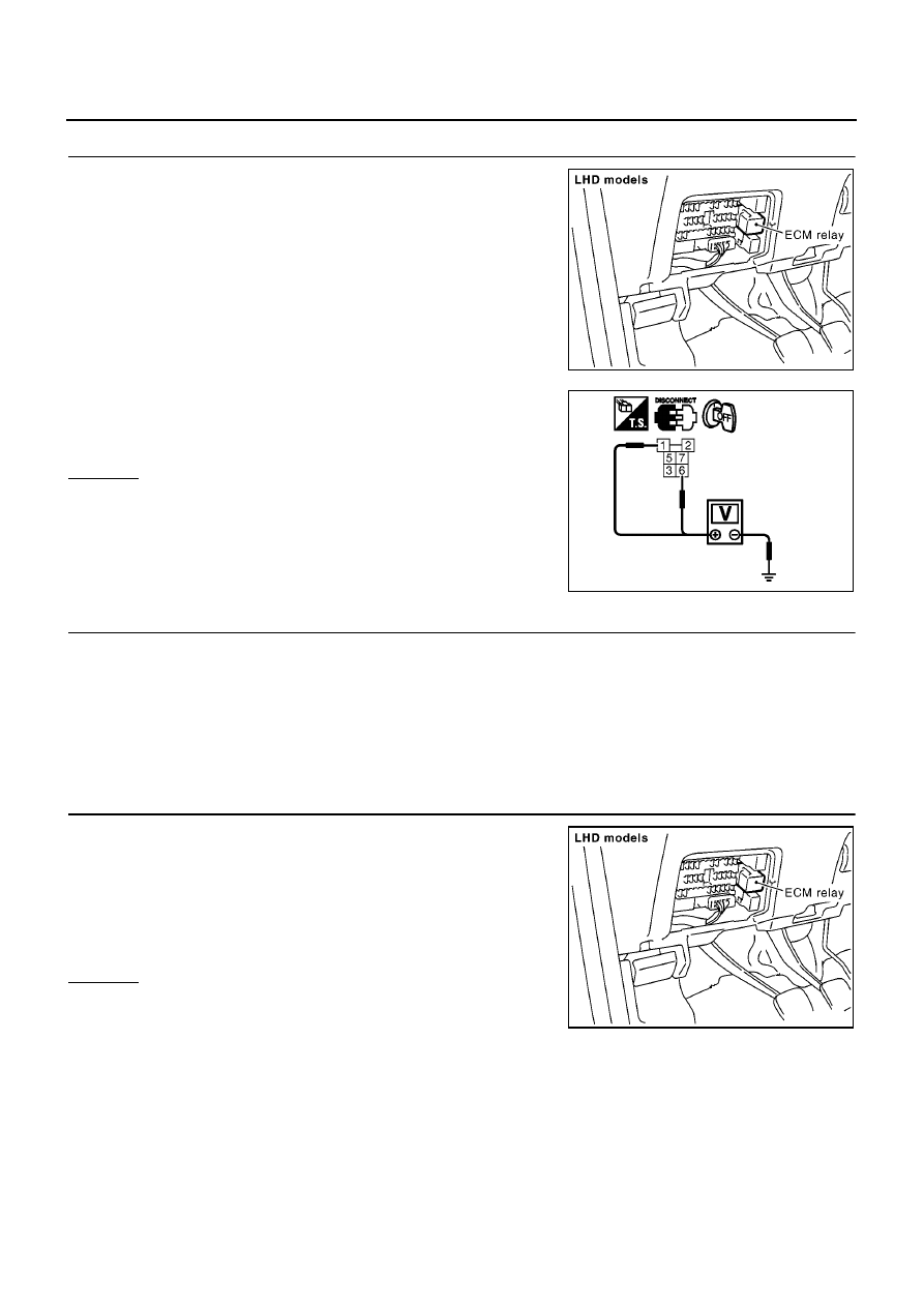
CHECK ECM POWER SUPPLY CIRCUIT-III

1.

Disconnect ECM relay.

2.

Check voltage between relay terminals 1, 6 and ground with
CONSULT-II or tester.

OK or NG

OK

>> GO TO 10.

NG

>> GO TO 9.

9.

DETECT MALFUNCTIONING PART

Check the following.

Harness connectors E105, M10

20A fuse

Harness for open or short between ECM relay and battery

>> Repair open circuit or short to ground or short to power in harness or connectors.

10.

CHECK OUTPUT SIGNAL CIRCUIT FOR OPEN AND SHORT

1.

Disconnect ECM relay.

2.

Disconnect ECM harness connector.

3.

Check harness continuity between ECM terminals 105, 113 and
ECM relay terminal 2. Refer to Wiring Diagram.

4.

Also check harness for short to ground and short to power.

OK or NG

OK

>> GO TO 11.

NG

>> Repair open circuit or short to ground or short to power

in harness or connectors.

MBIB0922E

Voltage: Battery voltage

PBIB0359E

Continuity should exist.

MBIB0922E

MAIN POWER SUPPLY AND GROUND CIRCUIT

EC-1315

[YD (WITHOUT EURO-OBD)]

C

D

E

F

G

H

I

J

K

L

M

A

EC

11.

CHECK ECM POWER SUPPLY CIRCUIT-IV

1.

Check harness continuity between ECM terminals 119, 120 and ECM relay terminal 7.
Refer to Wiring Diagram.

2.

Also check harness for short to ground and short to power.

OK or NG

OK

>> GO TO 12.

NG

>> Repair open circuit or short to ground or short to power in harness or connectors.

12.

CHECK ECM RELAY

Refer to

EC-1316, "Component Inspection"

.

OK or NG

OK

>> GO TO 13.

NG

>> Replace ECM relay.

13.

CHECK ECM POWER SUPPLY CIRCUIT-V

Check voltage between ECM terminal 121 and ground with CON-
SULT-II or tester.

OK or NG

OK

>> GO TO 15.

NG

>> GO TO 14.

14.

DETECT MALFUNCTIONING PART

Check the following.

20A fuse

Harness connectors E105, M10

Harness for open or short between ECM and fuse

>> Repair open circuit or short to ground or short to power in harness or connectors.

15.

CHECK GROUND CONNECTIONS

1.

Turn ignition switch OFF.

2.

Loosen and retighten body ground screw. Refer to

EC-1317,

"Ground Inspection"

.

OK or NG

OK

>> GO TO 16.

NG

>> Repair or replace ground connection.

Continuity should exist.

Voltage: Battery voltage

MBIB0026E

MBIB0915E

EC-1316

[YD (WITHOUT EURO-OBD)]

MAIN POWER SUPPLY AND GROUND CIRCUIT

16.

CHECK ECM GROUND CIRCUIT FOR OPEN AND SHORT

1.

Check harness continuity between ECM terminals 1, 2, 3, 114 and body ground.
Refer to Wiring Diagram.

2.

Also check harness for short to power.

OK or NG

OK

>> GO TO 17.

NG

>> Repair open circuit or short to power in harness or connectors.

17.

CHECK INTERMITTENT INCIDENT

Refer to

EC-1309, "TROUBLE DIAGNOSIS FOR INTERMITTENT INCIDENT"

.

>> INSPECTION END

Component Inspection

EBS014T9

ECM RELAY

1.

Apply 12V direct current between ECM relay terminals 1 and 2.

2.

Check continuity between relay terminals 3 and 5, 6 and 7.

3.

If NG, replace ECM relay.

Continuity should exist.

Condition

Continuity

12V direct current supply between terminals 1 and 2

Yes

OFF

No

PBIB0077E

MAIN POWER SUPPLY AND GROUND CIRCUIT

EC-1317

[YD (WITHOUT EURO-OBD)]

C

D

E

F

G

H

I

J

K

L

M

A

EC

Ground Inspection

EBS014TA

Ground connections are very important to the proper operation of electrical and electronic circuits. Ground
connections are often exposed to moisture, dirt and other corrosive elements. The corrosion (rust) can
become an unwanted resistance. This unwanted resistance can change the way a circuit works.
Electronically controlled circuits are very sensitive to proper grounding. A loose or corroded ground can drasti-
cally affect an electronically controlled circuit. A poor or corroded ground can easily affect the circuit. Even
when the ground connection looks clean, there can be a thin film of rust on the surface.
When inspecting a ground connection follow these rules:

Remove the ground bolt or screw.

Inspect all mating surfaces for tarnish, dirt, rust, etc.

Clean as required to assure good contact.

Reinstall bolt or screw securely.

Inspect for “add-on” accessories which may be interfering with the ground circuit.

If several wires are crimped into one ground eyelet terminal, check for proper crimps. Make sure all of the
wires are clean, securely fastened and providing a good ground path. If multiple wires are cased in one
eyelet make sure no ground wires have excess wire insulation.

For detailed ground distribution information, refer to EL-23, “GROUND”.

PBIB1870E


Content   ..  620  621  622  623   ..