Nissan Almera Tino V10. Manual - part 505
EC-846
[QG (WITHOUT EURO-OBD)]
HO2S1 (M/T MODELS)
Specification data are reference values and are measured between each terminal and ground.
CAUTION:
Do not use ECM ground terminals when measuring input/output voltage. Doing so may result in dam-
age to the ECM's transistor. Use a ground other than ECM terminals, such as the ground.
Diagnostic Procedure
EBS00R29
1.
INSPECTION START
Do you have CONSULT-II?
Yes or No
Yes
>> GO TO 2.
No
>> GO TO 3.
2.
CHECK OVERALL FUNCTION
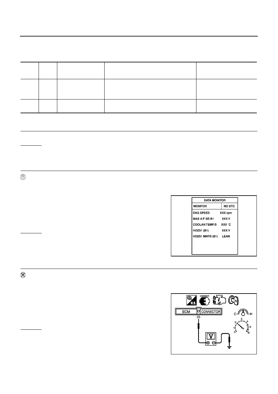
With CONSULT-II
1.
Start engine and warm it up to normal operating temperature.
2.
Select “HO2S1 MNTR (B1)” in “DATA MONITOR” mode with CONSULT-II.
3.
Keep the engine speed at 2,000 rpm under no load, and make
sure that the monitors fluctuate between LEAN and RICH more
than five times in 10 seconds.
OK or NG
OK
>> INSPECTION END
NG
>> GO TO 4.
3.
CHECK OVERALL FUNCTION
Without CONSULT-II
1.
Start engine and warm it up to normal operating temperature.
2.
Set voltmeter probes between ECM terminal 35 (HO2S1 signal) and engine ground.
3.
Keep the engine speed at 2,000 rpm under no load, and make
sure that the voltage fluctuates between 0 to 0.3V and 0.6 to
1.0V more than five times in 10 seconds.
OK or NG
OK
>> INSPECTION END
NG
>> GO TO 4.
TERMI-
NAL
NO.
WIRE
COLOR
ITEM
CONDITION
DATA (DC Voltage)
35
W
Heated oxygen sensor 1
[Engine is running]
●
Warm-up condition
●
Engine speed is 2,000 rpm.
0 - Approximately 1.0V
(Periodically change)
74
B
Sensors' ground
(Heated oxygen sensor)
[Engine is running]
●
Idle speed
Approximately 0V
1 time:
RICH
→
LEAN
→
RICH
2 times:
RICH
→
LEAN
→
RICH
→
LEAN
→
RICH
SEF646Y
1 time:
0 - 0.3V
→
0.6 - 1.0V
→
0 - 0.3V
2 times:
0 - 0.3V
→
0.6 - 1.0V
→
0 - 0.3V
→
0.6 - 1.0V
→
0 - 0.3V
MBIB0018E