Nissan Almera Tino V10. Manual - part 499
EC-822
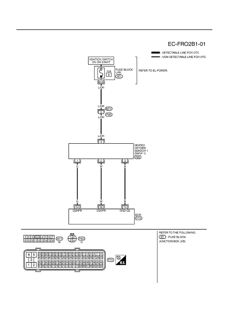
[QG (WITHOUT EURO-OBD)]
HO2S1 HEATER (A/T MODELS)
Wiring Diagram
EBS00R1L
BANK 1
YEC483A
|
|
|
EC-822 [QG (WITHOUT EURO-OBD)] HO2S1 HEATER (A/T MODELS) Wiring Diagram EBS00R1L BANK 1 YEC483A |