Nissan Almera Tino V10. Manual - part 498


  Index      Nissan     Nissan Almera Tino V10 - Service Manual (2003 year)


Search            


Content   ..  496  497  498  499   ..


Nissan Almera Tino V10. Manual - part 498


EC-818

[QG (WITHOUT EURO-OBD)]

HO2S1 HEATER (M/T MODELS)

Specification data are reference values and are measured between each terminal and ground.

CAUTION:

Do not use ECM ground terminals when measuring input/output voltage. Doing so may result in dam-
age to the ECM's transistor. Use a ground other than ECM terminals, such as the ground.

: Average voltage for pulse signal (Actual pulse signal can be confirmed by oscilloscope.)

Diagnostic Procedure

EBS00R1G

1.

CHECK OVERALL FUNCTION CHECK

1.

Start engine and warm it up to normal operating temperature.

2.

Turn ignition switch “OFF” and wait at least 10 seconds.

3.

Turn ignition switch “ON”.

4.

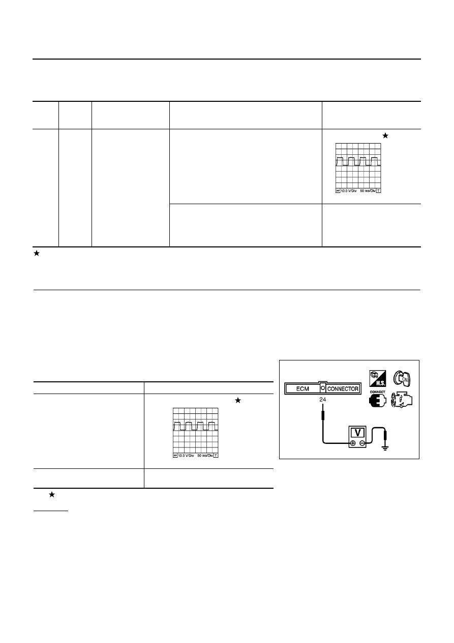
Set the tester probe between ECM terminal 24 (HO2S1 heater signal) and ground.

5.

Start engine and let it idle.

6.

Check the voltage under the following conditions.
Verify that the oscilloscope screen shows the signal wave as
shown below.

: Average voltage for pulse signal (Actual pulse signal can be confirmed by oscilloscope.)

OK or NG

OK

>> INSPECTION END.

NG

>> GO TO 2.

TER-

MINA

L NO.

WIRE

COLOR

ITEM

CONDITION

DATA (DC Voltage)

24

G

Heated oxygen sensor 1
heater

[Engine is running]

Warm-up condition.

Engine speed is below 3,600 rpm.

Approximately 7.0V

[Ignition switch “ON”]

Engine stopped.

[Engine is running]

Engine speed is above 3,600 rpm.

BATTERY VOLTAGE
(11 - 14V)

PBIB0519E

Conditions

Voltage

At idle

Approximately 7.0V

Engine speed is above 3,600 rpm

BATTERY VOLTAGE

(11 - 14V)

MBIB0038E

PBIB0519E

HO2S1 HEATER (M/T MODELS)

EC-819

[QG (WITHOUT EURO-OBD)]

C

D

E

F

G

H

I

J

K

L

M

A

EC

2.

CHECK HO2S1 POWER SUPPLY CIRCUIT

1.

Turn ignition switch “OFF”.

2.

Disconnect heated oxygen sensor 1 harness connector.

3.

Turn ignition switch “ON”.

4.

Check voltage between HO2S1 terminal 4 and ground with
CONSULT-II or tester.

OK or NG

OK

>> GO TO 4.

NG

>> GO TO 3.

3.

DETECT MALFUNCTIONING PART

Check the following.

Harness connectors M71, F45

Fuse block (J/B) connector M1

10A fuse

Harness for open or short between heated oxygen sensor 1 and fuse

>> Repair open circuit or short to ground or short to power in harness or connectors.

4.

CHECK HO2S1 OUTPUT SIGNAL CIRCUIT FOR OPEN AND SHORT

1.

Turn ignition switch “OFF”.

2.

Disconnect ECM harness connector.

3.

Check harness continuity between ECM terminal 24 and HO2S1 terminal 1.
Refer to Wiring Diagram.

4.

Also check harness for short to ground and short to power.

OK or NG

OK

>> GO TO 5.

NG

>> Repair open circuit or short to ground or short to power in harness or connectors.

5.

CHECK HEATED OXYGEN SENSOR 1 HEATER

Refer to

EC-820, "Component Inspection"

.

OK or NG

OK

>> GO TO 6.

NG

>> Replace heated oxygen sensor 1.

MBIB0091E

Voltage: Battery voltage

PBIB0541E

Continuity should exist.

EC-820

[QG (WITHOUT EURO-OBD)]

HO2S1 HEATER (M/T MODELS)

6.

CHECK INTERMITTENT INCIDENT

Refer to

EC-644, "TROUBLE DIAGNOSIS FOR INTERMITTENT INCIDENT"

.

>> INSPECTION END

Component Inspection

EBS00R1H

HEATED OXYGEN SENSOR 1 HEATER

1.

Check resistance between HO2S1 terminals as follows.

2.

If NG, replace heated oxygen sensor 1.

CAUTION:

Discard any heated oxygen sensor which has been dropped
from a height of more than 0.5 m (19.7 in) onto a hard sur-
face such as a concrete floor; use a new one.

Before installing new oxygen sensor, clean exhaust system
threads using Oxygen Sensor Thread Cleaner tool J-43897-
18 or J-43897-12 and approved anti-seize lubricant.

Removal and Installation

EBS00R1I

HEATED OXYGEN SENSOR 1

Refer to

EM-21, "EXHAUST MANIFOLD AND CATALYTIC CONVERTER"

.

Terminal No.

Resistance

1 and 4

8 - 10

at 25

°

C (77

°

F)

2 and 3, 4

∞ Ω

(Continuity should not exist)

3 and 1, 2, 4

PBIB0542E

HO2S1 HEATER (A/T MODELS)

EC-821

[QG (WITHOUT EURO-OBD)]

C

D

E

F

G

H

I

J

K

L

M

A

EC

HO2S1 HEATER (A/T MODELS)

PFP:22690

Description

EBS00R1J

SYSTEM DESCRIPTION

The ECM performs ON/OFF duty control of the heated oxygen sensor 1 heater corresponding to the engine
speed and engine coolant temperature. The duty percent varies with engine coolant temperature when engine
is started.

OPERATION

CONSULT-II Reference Value in Data Monitor Mode

EBS00R1K

Specification data are reference values.

Sensor

Input Signal to ECM

ECM function

Actuator

Camshaft position sensor (PHASE)
Crankshaft position sensor (POS)

Engine speed

Heated oxygen sensor 1
heater control

Heated oxygen sensor 1
heater

Engine coolant temperature sensor

Engine coolant temperature

Engine speed rpm

Heated oxygen sensor 1 heater

Above 3,200

OFF

Below 3,200 after warming up

ON

MONITOR ITEM

CONDITION

SPECIFICATION

HO2S1 HTR (B1)
HO2S1 HTR (B2)

Engine: After warming up

Engine speed: Below 3,200 rpm

ON

Engine speed: Above 3,200 rpm

OFF


Content   ..  496  497  498  499   ..