Nissan Almera Tino V10. Manual - part 500


  Index      Nissan     Nissan Almera Tino V10 - Service Manual (2003 year)


Search            


Content   ..  498  499  500  501   ..


Nissan Almera Tino V10. Manual - part 500


EC-826

[QG (WITHOUT EURO-OBD)]

HO2S1 HEATER (A/T MODELS)

2.

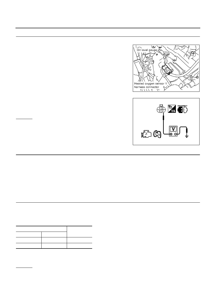
CHECK HO2S1 POWER SUPPLY CIRCUIT

1.

Turn ignition switch “OFF”.

2.

Disconnect heated oxygen sensor 1 harness connector.

3.

Turn ignition switch “ON”.

4.

Check voltage between HO2S1 terminal 4 and ground with
CONSULT-II or tester.

OK or NG

OK

>> GO TO 4.

NG

>> GO TO 3.

3.

DETECT MALFUNCTIONING PART

Check the following.

Harness connectors M71, F45

Fuse block (J/B) connector M1

10A fuse

Harness for open or short between heated oxygen sensor 1 and fuse

>> Repair open circuit or short to ground or short to power in harness or connectors.

4.

CHECK HO2S1 OUTPUT SIGNAL CIRCUIT FOR OPEN AND SHORT

1.

Turn ignition switch “OFF”.

2.

Disconnect ECM harness connector.

3.

Check harness continuity between ECM terminal and HO2S1 terminal as follows.
Refer to Wiring Diagram.

4.

Also check harness for short to ground and short to power.

OK or NG

OK

>> GO TO 5.

NG

>> Repair open circuit or short to ground or short to power in harness or connectors.

MBIB0091E

Voltage: Battery voltage

PBIB0541E

Terminals

Bank

ECM

Sensor

24

1

1

25

1

2

Continuity should exist.

HO2S1 HEATER (A/T MODELS)

EC-827

[QG (WITHOUT EURO-OBD)]

C

D

E

F

G

H

I

J

K

L

M

A

EC

5.

CHECK HEATED OXYGEN SENSOR 1 HEATER

Refer to

EC-827, "Component Inspection"

.

OK or NG

OK

>> GO TO 6.

NG

>> Replace heated oxygen sensor 1.

6.

CHECK INTERMITTENT INCIDENT

Refer to

EC-644, "TROUBLE DIAGNOSIS FOR INTERMITTENT INCIDENT"

.

>> INSPECTION END

Component Inspection

EBS00R1N

HEATED OXYGEN SENSOR 1 HEATER

1.

Check resistance between HO2S1 terminals as follows.

2.

If NG, replace heated oxygen sensor 1.

CAUTION:

Discard any heated oxygen sensor which has been dropped
from a height of more than 0.5 m (19.7 in) onto a hard sur-
face such as a concrete floor; use a new one.

Before installing new oxygen sensor, clean exhaust system
threads using Oxygen Sensor Thread Cleaner tool J-43897-
18 or J-43897-12 and approved anti-seize lubricant.

Removal and Installation

EBS00R1O

HEATED OXYGEN SENSOR 1

Refer to

EM-21, "EXHAUST MANIFOLD AND CATALYTIC CONVERTER"

.

Terminal No.

Resistance

1 and 4

8 - 10

at 25

°

C (77

°

F)

2 and 3, 4

∞ Ω

(Continuity should not exist)

3 and 1, 2, 4

PBIB0542E

EC-828

[QG (WITHOUT EURO-OBD)]

HO2S2 HEATER (M/T MODELS)

HO2S2 HEATER (M/T MODELS)

PFP:226A0

Description

EBS00R1P

SYSTEM DESCRIPTION

The ECM performs ON/OFF control of the heated oxygen sensor 2 heater corresponding to the engine speed,
amount of intake air and engine coolant temperature.

OPERATION

CONSULT-II Reference Value in Data Monitor Mode

EBS00R1Q

Specification data are reference values.

Sensor

Input Signal to ECM

ECM function

Actuator

Camshaft position sensor (PHASE)
Crankshaft position sensor (POS)

Engine speed

Heated oxygen sensor 2
heater control

Heated oxygen sensor 2 heater

Engine coolant temperature sensor

Engine coolant temperature

Mass air flow sensor

Amount of intake air

Engine speed rpm

Heated oxygen sensor 2 heater

Above 3,800

OFF

Below 3,800 rpm after the following conditions are met.

Engine: After warming up

Keeping the engine speed between 3,500 and 4,000 rpm for
one minute and at idle for one minute under no load

ON

MONITOR ITEM

CONDITION

SPECIFICATION

HO2S2 HTR (B1)

Engine speed: Below 3,800 rpm after the following conditions are met.

Engine: After warming up

Keeping the engine speed between 3,500 and 4,000 rpm for one
minute and at idle for one minute under no load

ON

Engine speed: Above 3,800 rpm

OFF

HO2S2 HEATER (M/T MODELS)

EC-829

[QG (WITHOUT EURO-OBD)]

C

D

E

F

G

H

I

J

K

L

M

A

EC

Wiring Diagram

EBS00R1R

YEC485A


Content   ..  498  499  500  501   ..