Nissan Almera Tino V10. Manual - part 439


  Index      Nissan     Nissan Almera Tino V10 - Service Manual (2003 year)


Search            


Content   ..  437  438  439  440   ..


Nissan Almera Tino V10. Manual - part 439


EC-582

[QG (WITHOUT EURO-OBD)]

ON BOARD DIAGNOSTIC (OBD) SYSTEM

How to Read DTC and 1st Trip DTC

DTC and 1st trip DTC can be read by the following methods.

With CONSULT-II

CONSULT-II displays the DTC in “SELF-DIAG RESULTS” mode. Examples: P0117, P0340, P1065, etc.
(CONSULT-II also displays the malfunctioning component or system.)

Without CONSULT-II

The number of blinks of the MI in the Diagnostic Test Mode II (Self-Diagnostic Results) indicates the DTC.
Example: 0117, 0340 1065 etc.

1st trip DTC No. is the same as DTC No.

Output of a DTC indicates a malfunction. However, the Diagnostic Test Mode II does not indicate
whether the malfunction is still occurring or has occurred in the past and has returned to normal.
CONSULT-II can identify malfunction status as shown below. Therefore, using CONSULT-II (if avail-
able) is recommended.

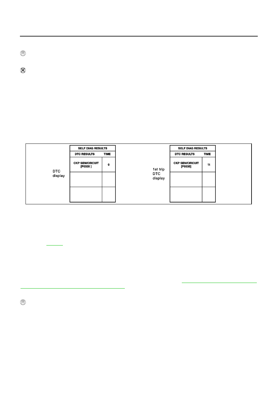
A sample of CONSULT-II display for DTC and 1st trip DTC is shown below. DTC or 1st trip DTC of a malfunc-
tion is displayed in SELF-DIAGNOSTIC RESULTS mode of CONSULT-II. Time data indicates how many times
the vehicle was driven after the last detection of a DTC.
If the DTC is being detected currently, the time data will be “0”.
If a 1st trip DTC is stored in the ECM, the time data will be “[1t]”.

FREEZE FRAME DATA AND 1ST TRIP FREEZE FRAME DATA

The ECM records the driving conditions such as fuel system status, calculated load value, engine coolant tem-
perature, short term fuel trim, long term fuel trim, engine speed, vehicle speed, base fuel schedule and intake
air temperature at the moment a malfunction is detected.
Data which are stored in the ECM memory, along with the 1st trip DTC, are called 1st trip freeze frame data.
The data, stored together with the DTC data, are called freeze frame data and displayed on CONSULT-II. For
details, see

EC-627

.

Only one set of freeze frame data (either 1st trip freeze frame data or freeze frame data) can be stored in the
ECM. 1st trip freeze frame data is stored in the ECM memory along with the 1st trip DTC. There is no priority
for 1st trip freeze frame data and it is updated each time a different 1st trip DTC is detected. However, once
freeze frame data (2nd trip detection/MI on) is stored in the ECM memory, 1st trip freeze frame data is no
longer stored. Remember, only one set of freeze frame data can be stored in the ECM.
Both 1st trip freeze frame data and freeze frame data (along with the DTCs) are cleared when the ECM mem-
ory is erased. Procedures for clearing the ECM memory are described in

EC-582, "HOW TO ERASE EMIS-

SION-RELATED DIAGNOSTIC INFORMATION"

.

HOW TO ERASE EMISSION-RELATED DIAGNOSTIC INFORMATION

How to Erase DTC ( With CONSULT-II)

The emission related diagnostic information in the ECM can be erased by selecting “ERASE” in the “SELF-
DIAG RESULTS” mode with CONSULT-II.

1.

If the ignition switch stays “ON” after repair work, be sure to turn ignition switch “OFF” once. Wait at least
10 seconds and then turn it “ON” (engine stopped) again.

2.

Touch “ENGINE”.

3.

Touch “SELF-DIAG RESULTS”.

PBIB0911E

ON BOARD DIAGNOSTIC (OBD) SYSTEM

EC-583

[QG (WITHOUT EURO-OBD)]

C

D

E

F

G

H

I

J

K

L

M

A

EC

4.

Touch “ERASE”. (The DTC in the ECM will be erased.)

How to Erase DTC ( Without CONSULT-II)

1.

If the ignition switch stays “ON” after repair work, be sure to turn ignition switch “OFF” once.

2.

Wait at least 10 seconds and then turn it “ON” (engine stopped) again.

3.

Change the diagnostic test mode from Mode II to Mode I by depressing the accelerator pedal. Refer to

EC-585, "HOW TO SWITCH DIAGNOSTIC TEST MODE"

.

If the battery is disconnected, the emission-related diagnostic information will be lost after
approx. 24 hours.

The following data are cleared when the ECM memory is erased.

Diagnostic trouble codes

1st trip diagnostic trouble codes

Freeze frame data

1st trip freeze frame data

Others

Actual work procedures are explained using a DTC as an example. Be careful so that not only the DTC, but all
of the data listed above, are cleared from the ECM memory during work procedures.

NATS (Nissan Anti-theft System)

EBS00QV4

If the security indicator lights up with the ignition switch in
the “ON” position or “NATS MALFUNCTION” is displayed
on “SELF-DIAG RESULTS” screen, perform self-diagnostic
results mode with CONSULT-II using NATS program card.
Refer to “NATS (NISSAN ANTI-THEFT SYSTEM)”, EL-352.

Confirm no self-diagnostic results of NATS is displayed
before touching “ERASE” in “SELF-DIAG RESULTS” mode
with CONSULT-II.

When replacing ECM, initialization of NATS system and reg-
istration of all NATS ignition key IDs must be carried out
with CONSULT-II using NATS program card.
Therefore, be sure to receive all keys from vehicle owner.
Regarding the procedures of NATS initialization and NATS ignition key ID registration, refer to
CONSULT-II operation manual, NATS.

PBIB0671E

SEF515Y

EC-584

[QG (WITHOUT EURO-OBD)]

ON BOARD DIAGNOSTIC (OBD) SYSTEM

Malfunction Indicator (MI)

EBS00QV5

DESCRIPTION

The MI is located on the instrument panel.

1.

The MI will light up when the ignition switch is turned ON without
the engine running. This is a bulb check.
If the MI does not light up, refer to “WARNING LAMPS”, EL-115
or see

EC-929

.

2.

When the engine is started, the MI should go off.
If the MI remains on, the on board diagnostic system has
detected an engine system malfunction.

ON BOARD DIAGNOSTIC SYSTEM FUNCTION

The on board diagnostic system has the following four functions.

When there is an open circuit on MI circuit, the ECM can not warn the driver by lighting up MI when there is
malfunction on engine control system.
Therefore, when electrical controlled throttle and part of ECM related diagnoses are continuously detected as
NG for 5 trips, ECM warns the driver that engine control system has trouble and MI circuit is open by means of
operating fail-safe function.
The fail-safe function also operate when above diagnoses except MI circuit are detected and demands the
driver to repair the trouble.

SAT652J

Diagnostic Test
Mode

KEY and ENG.
Status

Function

Explanation of Function

Mode I

Ignition switch in
“ON” position

Engine stopped

BULB CHECK

This function checks the MI bulb for damage (blown, open
circuit, etc.).
If the MI does not come on, check MI circuit.

Engine running

MALFUNCTION
WARNING

This is a usual driving condition. When a malfunction is
detected twice in two consecutive driving cycles (two trip
detection logic), the MI will light up to inform the driver that
a malfunction has been detected.
The following malfunctions will light up the MI in the 1st
trip.

“One trip detection diagnoses”

Mode II

Ignition switch in
“ON” position

Engine stopped

SELF-DIAGNOSTIC
RESULTS

This function allows DTCs and 1st trip DTCs to be read.

Engine running

HEATED OXYGEN SENSOR 1
MONITOR

This function allows the fuel mixture condition (lean or
rich), monitored by heated oxygen sensor 1, to be read.

Engine operating condition in fail-safe mode

Engine speed will not rise more than 2,500 rpm due to the fuel cut

ON BOARD DIAGNOSTIC (OBD) SYSTEM

EC-585

[QG (WITHOUT EURO-OBD)]

C

D

E

F

G

H

I

J

K

L

M

A

EC

MI Flashing without DTC

If the ECM is in Diagnostic Test Mode II, MI may flash when engine is running. In this case, check ECM diag-
nostic test mode. Refer to

EC-585, "HOW TO SWITCH DIAGNOSTIC TEST MODE"

.

How to switch the diagnostic test (function) modes, and details of the above functions are described later

EC-

585, "HOW TO SWITCH DIAGNOSTIC TEST MODE"

.

The following emission-related diagnostic information is cleared when the ECM memory is erased.

Diagnostic trouble codes

1st trip diagnostic trouble codes

Freeze frame data

1st trip freeze frame data

Others

HOW TO SWITCH DIAGNOSTIC TEST MODE

NOTE:

It is better to count the time accurately with a clock.

It is impossible to switch the diagnostic mode when an accelerator pedal position sensor circuit
has a malfunction.

Always ECM returns to Diagnostic Test Mode I after ignition switch is turned “OFF”.

How to Set Diagnostic Test Mode II (Self-diagnostic Results)

1.

Confirm that accelerator pedal is fully released, turn ignition switch “ON” and wait 3 seconds.

2.

Repeat the following procedure quickly five times within 5 seconds.

a.

Fully depress the accelerator pedal.

b.

Fully release the accelerator pedal.

3.

Wait 7 seconds, fully depress the accelerator pedal and keep it for approx. 10 seconds until the MI starts
blinking.

4.

Fully release the accelerator pedal.
ECM has entered to Diagnostic Test Mode II (Self-diagnostic results).

How to Set Diagnostic Test Mode II (Heated Oxygen Sensor 1 Monitor)

1.

Set the ECM in Diagnostic Test Mode II (Self-diagnostic results). Refer to

EC-585, "How to Set Diagnostic

Test Mode II (Self-diagnostic Results)"

.

2.

Start Engine.
ECM has entered to Diagnostic Test Mode II (Heated oxygen sensor 1 monitor).
ECM will start heated oxygen sensor 1 monitoring from the bank 1 sensor for A/T models.

How to Switch Monitored Sensor From Bank 1 to Bank 2 or Vice Versa

1.

Fully depress the accelerator pedal quickly and then release it immediately.

PBIB0092E


Content   ..  437  438  439  440   ..