Nissan Almera Tino V10. Manual - part 440


  Index      Nissan     Nissan Almera Tino V10 - Service Manual (2003 year)


Search            


Content   ..  438  439  440  441   ..


Nissan Almera Tino V10. Manual - part 440


EC-586

[QG (WITHOUT EURO-OBD)]

ON BOARD DIAGNOSTIC (OBD) SYSTEM

2.

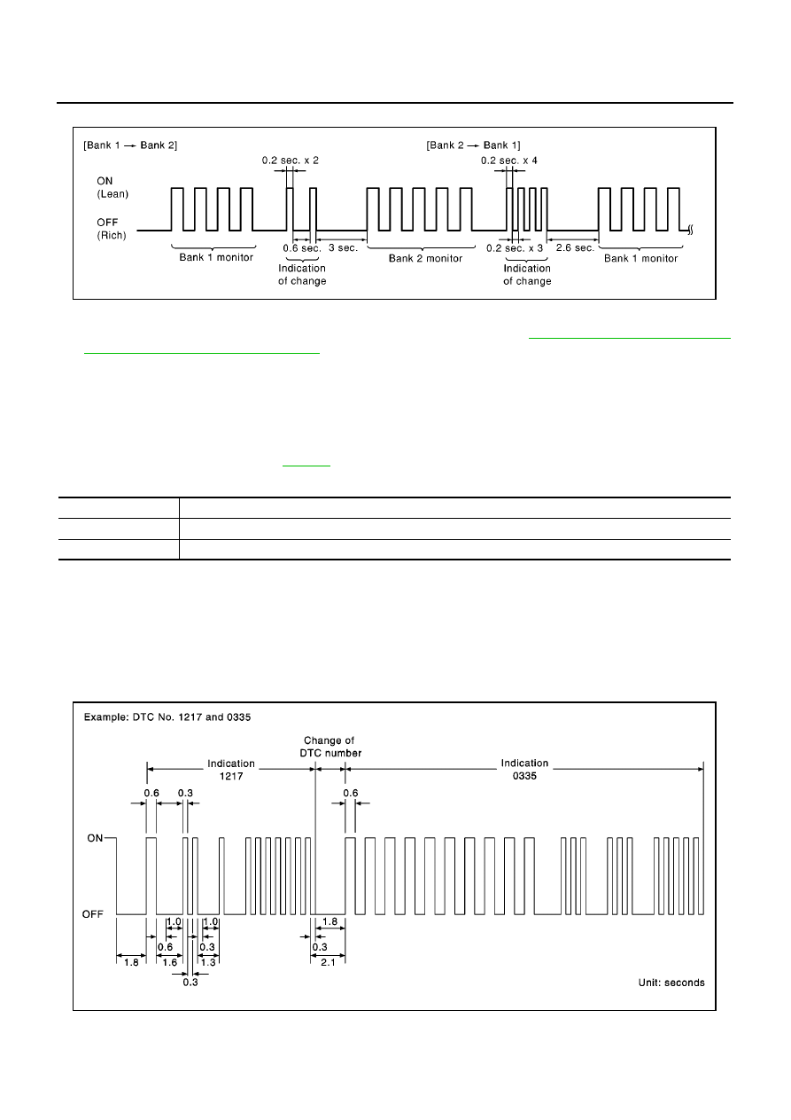
Make sure that monitoring sensor has changed by MI blinking as follows.

How to Erase Diagnostic Test Mode II (Self-diagnostic Results)

1.

Set ECM in Diagnostic Test Mode II (Self-diagnostic results). Refer to

EC-585, "How to Set Diagnostic

Test Mode II (Self-diagnostic Results)"

.

2.

Fully depress the accelerator pedal and keep it for more than 10 seconds.
The emission-related diagnostic information has been erased from the backup memory in the ECM.

3.

Fully release the accelerator pedal, and confirm the DTC 0000 is displayed.

DIAGNOSTIC TEST MODE I — BULB CHECK

In this mode, the MI on the instrument panel should stay ON. If it remains OFF, check the bulb. Refer to
“WARNING LAMPS”, EL-115 or see

EC-929

.

DIAGNOSTIC TEST MODE I — MALFUNCTION WARNING

These DTC numbers are clarified in Diagnostic Test Mode II (SELF-DIAGNOSTIC RESULTS)

DIAGNOSTIC TEST MODE II — SELF-DIAGNOSTIC RESULTS

In this mode, the DTC and 1st trip DTC are indicated by the number of blinks of the MI as shown below.
The DTC and 1st trip DTC are displayed at the same time. If the MI does not illuminate in diagnostic test mode
I (Malfunction warning), all displayed items are 1st trip DTCs. If only one code is displayed when the MI illumi-
nates in diagnostic test mode II (SELF-DIAGNOSTIC RESULTS), it is a DTC; if two or more codes are dis-
played, they may be either DTCs or 1st trip DTCs. DTC No. is same as that of 1st trip DTC. These unidentified
codes can be identified by using the CONSULT-II. A DTC will be used as an example for how to read a code.

PBIB0093E

MI

Condition

ON

When the malfunction is detected.

OFF

No malfunction.

PBIA3905E

ON BOARD DIAGNOSTIC (OBD) SYSTEM

EC-587

[QG (WITHOUT EURO-OBD)]

C

D

E

F

G

H

I

J

K

L

M

A

EC

A particular trouble code can be identified by the number of four-digit numeral flashes. The “zero” is indicated
by the number of ten flashes. The length of time the 1,000th-digit numeral flashes on and off is 1.2 seconds
consisting of an ON (0.6-second) - OFF (0.6-second) cycle.
The 100th-digit numeral and lower digit numerals consist of a 0.3-second ON and 0.3-second OFF cycle.
A change from one digit numeral to another occurs at an interval of 1.0-second OFF. In other words, the later
numeral appears on the display 1.3 seconds after the former numeral has disappeared.
A change from one trouble code to another occurs at an interval of 1.8-second OFF.
In this way, all the detected malfunctions are classified by their DTC numbers. The DTC “0000” refers to no
malfunction. (See

EC-554, "INDEX FOR DTC"

)

How to Erase Diagnostic Test Mode II (Self-diagnostic Results)

The DTC can be erased from the back up memory in the ECM by depressing accelerator pedal. Refer to

EC-

585, "HOW TO SWITCH DIAGNOSTIC TEST MODE"

.

If the battery is disconnected, the DTC will be lost from the backup memory after approx 24 hours.

Be careful not to erase the stored memory before starting trouble diagnoses.

DIAGNOSTIC TEST MODE II — HEATED OXYGEN SENSOR 1 MONITOR

In this mode, the MI displays the condition of the fuel mixture (lean or rich) which is monitored by the heated
oxygen sensor 1.

*: Maintains conditions just before switching to open loop.

To check the heated oxygen sensor 1 function, start engine in the Diagnostic Test Mode II and warm it up until
engine coolant temperature indicator points to the middle of the gauge.
Next run engine at about 2,000 rpm for about 2 minutes under no-load conditions. Then make sure that the MI
comes ON more than 5 times within 10 seconds with engine running at 2,000 rpm under no-load.

MI

Fuel mixture condition in the exhaust gas

Air fuel ratio feedback control condition

ON

Lean

Closed loop system

OFF

Rich

*Remains ON or OFF

Any condition

Open loop system

EC-588

[QG (WITHOUT EURO-OBD)]

TROUBLE DIAGNOSIS

TROUBLE DIAGNOSIS

PFP:00004

Trouble Diagnosis Introduction

EBS00QV6

INTRODUCTION

The engine has an ECM to control major systems such as fuel con-
trol, ignition control, idle air control system, etc. The ECM accepts
input signals from sensors and instantly drives actuators. It is essen-
tial that both input and output signals are proper and stable. At the
same time, it is important that there are no malfunctions such as vac-
uum leaks, fouled spark plugs, or other malfunctions with the engine.
It is much more difficult to diagnose a incident that occurs intermit-
tently rather than continuously. Most intermittent incidents are
caused by poor electric connections or improper wiring. In this case,
careful checking of suspected circuits may help prevent the replace-
ment of good parts.
A visual check only may not find the cause of the incidents. A road
test with CONSULT-II or a circuit tester connected should be per-
formed. Follow the “Work Flow” on

EC-589

.

Before undertaking actual checks, take a few minutes to talk with a
customer who approaches with a driveability complaint. The cus-
tomer can supply good information about such incidents, especially
intermittent ones. Find out what symptoms are present and under
what conditions they occur. A “Diagnostic Worksheet” like the exam-
ple on

EC-592

should be used.

Start your diagnosis by looking for “conventional” malfunctions first.
This will help troubleshoot driveability malfunctions on an electroni-
cally controlled engine vehicle.

MEF036D

SEF233G

SEF234G

TROUBLE DIAGNOSIS

EC-589

[QG (WITHOUT EURO-OBD)]

C

D

E

F

G

H

I

J

K

L

M

A

EC

WORK FLOW
Flow Chart

*1

If time data of “SELF-DIAG
RESULTS” is other than “0” or “[1t]”,
perform

EC-644, "TROUBLE DIAG-

NOSIS FOR INTERMITTENT INCI-
DENT"

.

*2

If time data of “SELF-DIAG
RESULTS” is other than “0” or “[1t]”,
perform

EC-644, "TROUBLE DIAG-

NOSIS FOR INTERMITTENT INCI-
DENT"

.

*3

If the on board diagnostic system
cannot be performed, check main
power supply and ground circuit.
Refer to

EC-645, "POWER SUPPLY

CIRCUIT FOR ECM"

.

*4

If the incident cannot be verified, per-
form

EC-644, "TROUBLE DIAGNO-

SIS FOR INTERMITTENT
INCIDENT"

.

*5

EC-640, "TROUBLE DIAGNOSIS -
SPECIFICATION VALUE"

MBIB0178E


Content   ..  438  439  440  441   ..