Nissan Almera Tino V10. Manual - part 172


  Index      Nissan     Nissan Almera Tino V10 - Service Manual (2003 year)


Search            


Content   ..  170  171  172  173   ..


Nissan Almera Tino V10. Manual - part 172


AT-412

[ALL]

ON-VEHICLE SERVICE

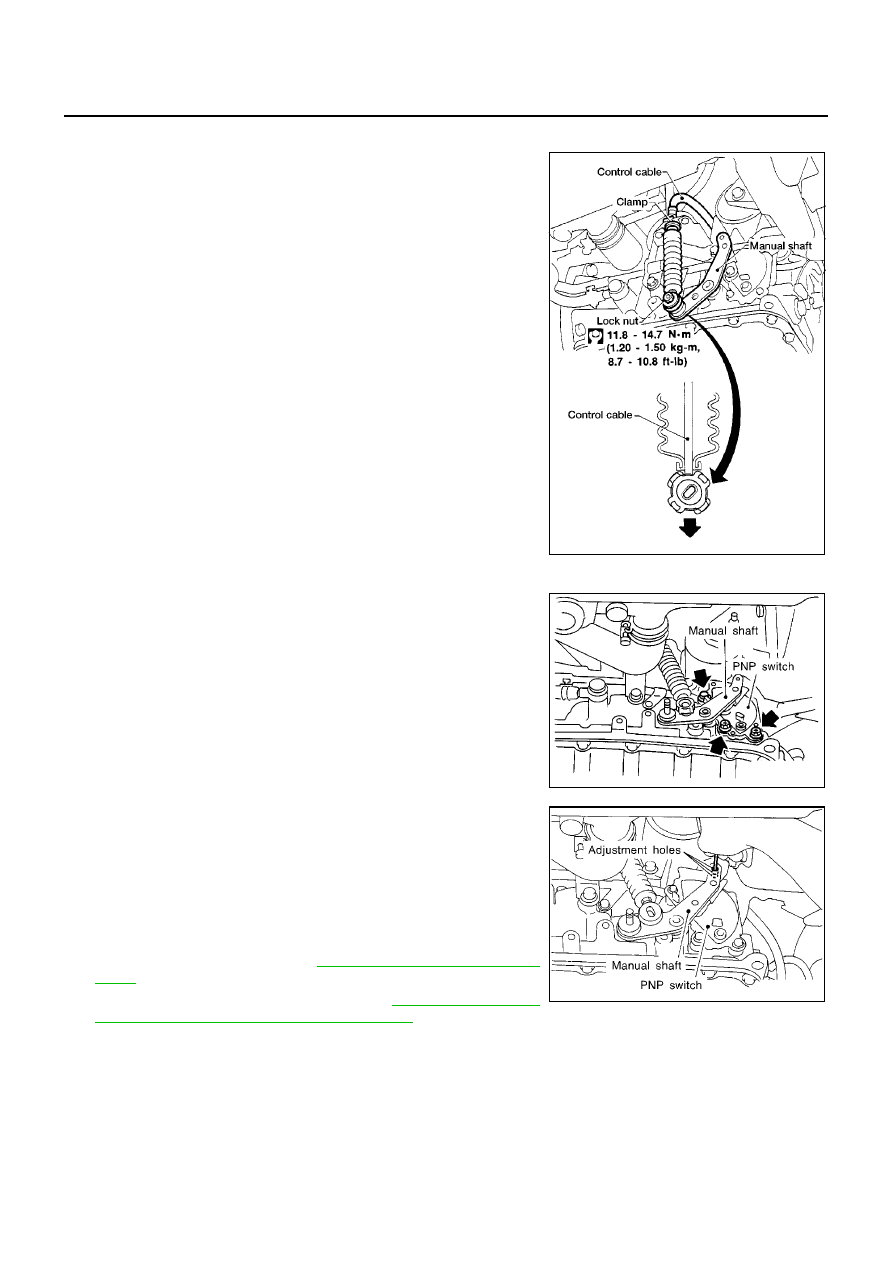
Control Cable Adjustment

ECS009C7

Move selector lever from the “P” position to the “1” position. You
should be able to feel the detentes in each position. If the detentes
cannot be felt or if the pointer indicating the position is improperly
aligned, the control cable needs adjustment.

1.

Place selector lever in “P” position.

2.

Loosen control cable lock nut and place manual shaft in “P”
position.

3.

Pull control cable, by specified force, in the direction of the arrow
shown in the illustration.

4.

Return control cable in the opposite direction of the arrow for 1.0
mm (0.039 in).

5.

Tighten control cable lock nut.

6.

Move selector lever from “P” to “1” position again. Make sure
that selector lever moves smoothly.

7.

Apply grease to contacting areas of selector lever and control
cable. Install any part removed.

Park/Neutral Position (PNP) Switch Adjustment

ECS009C8

1.

Remove control cable end from manual shaft.

2.

Set manual shaft in “N” position.

3.

Loosen PNP switch fixing bolts.

4.

Use a 4 mm (0.157 in) pin for this adjustment.

a.

Insert the pin straight into the manual shaft adjustment hole.

b.

Rotate PNP switch until the pin can also be inserted straight into
hole in PNP switch.

5.

Tighten PNP switch fixing bolts.

6.

Remove pin from adjustment hole after adjusting PNP switch.

7.

Reinstall any part removed.

8.

Adjust control cable. Refer to

AT-412, "Control Cable Adjust-

ment"

.

9.

Check continuity of PNP switch. Refer to

AT-113, "DTC P0705

PARK/NEUTRAL POSITION (PNP) SWITCH"

.

Specified force: 6.9 N (0.7 kg, 1.5 lb)

AAT980

SAT479J

SAT480J

ON-VEHICLE SERVICE

AT-413

[ALL]

D

E

F

G

H

I

J

K

L

M

A

B

AT

Differential Side Oil Seal Replacement

ECS009C9

1.

Remove drive shaft assemblies. Refer to AX-10, “Drive Shaft”.

2.

Remove oil seals.

3.

Install oil seals.

Apply ATF to oil seal surface before installing.

Drift for installing

Install oil seals so that dimensions “A” and “B” are within
specifications.

Unit: mm (in)

4.

Reinstall any part removed.

Revolution Sensor Replacement

ECS009CA

1.

Disconnect revolution sensor harness connector.

2.

Remove harness bracket from A/T.

3.

Remove revolution sensor from A/T.

4.

Reinstall any part removed.

Always use new sealing parts.

SAT905D

AAT976

A

B

5.5 to 6.5 (0.217 to 0.256)

0.5 to 0.5 (

0.020 to 0.020)

MCIB9018E

SAT303G

AT-414

[ALL]

REMOVAL AND INSTALLATION

REMOVAL AND INSTALLATION

PFP:00000

Removal

ECS009CB

CAUTION:

Before separating transaxle from engine, remove the crankshaft
position sensor (OBD) from transaxle. Be careful not to damage
sensor.

1.

Remove battery and bracket.

2.

Remove air duct between throttle body and air cleaner.

3.

Disconnect A/T solenoid harness connector, PNP switch har-
ness connector and revolution sensor harness connector.

4.

Remove crankshaft position sensor (OBD) from transaxle.

5.

Drain ATF from transaxle.

6.

Disconnect control cable from transaxle.

7.

Disconnect fluid cooler hoses.

8.

Remove drive shafts. Refer to AX-10, “Drive Shaft”.

9.

Remove the intake manifold support bracket.

10. Remove starter motor from transaxle.

11. Remove upper bolts fixing transaxle to engine.
12. Support transaxle with a jack.

13. Remove center member.

14. Remove center member, engine insulator and engine mounting bracket.

SAT501HA

Tighten bolts to specified torque.

: 41 - 52 N-m (4.2 - 5.3 kg-m, 30 - 38 ft-lb)

SAT304G

AAT469

REMOVAL AND INSTALLATION

AT-415

[ALL]

D

E

F

G

H

I

J

K

L

M

A

B

AT

15. Remove dust cover from converter housing.

Rotate crankshaft to gain access to securing bolts.

16. Remove securing bolts between drive plate and torque con-

verter. when crank shaft rotates, turn to right at the front side of
engine.

17. Support engine with a jack.

18. Remove bolts fixing transaxle to engine.

19. Lower transaxle while supporting it with a jack.

Installation

ECS009CC

1.

Check drive plate runout.

CAUTION:

Do not allow any magnetic materials to contact the ring
gear teeth.

If this runout is out of allowance, replace drive plate with ring
gear.

2.

When connecting torque converter to transaxle, measure dis-
tance “A” to be certain that they are correctly assembled.

3.

Install torque converter to drive plate.

With converter installed, rotate crankshaft several turns
to check that transaxle rotates freely without binding.

AAT259A

Maximum allowable runout

:

Refer to

EM-95, "FLYWHEEL RUNOUT"

.

SAT977H

Distance “A”: 21.1 mm (0.831 in) or more

SAT573D

AAT266A


Content   ..  170  171  172  173   ..