Nissan Almera Tino V10. Manual - part 164
 

  Index      Nissan     Nissan Almera Tino V10 - Service Manual (2003 year)


Search            


Content   ..  162  163  164  165   ..


Nissan Almera Tino V10. Manual - part 164


AT-380

[ALL]

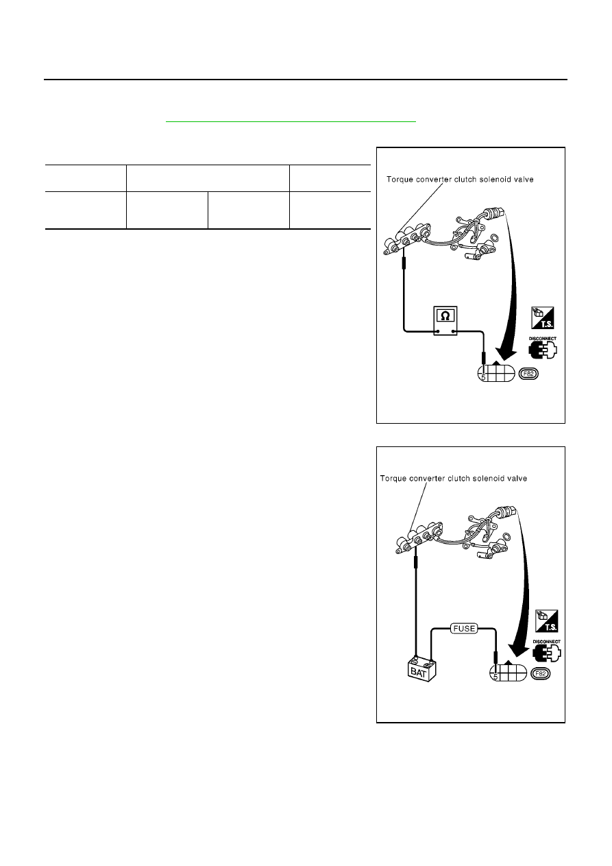
TORQUE CONVERTER CLUTCH SOLENOID VALVE

Component Inspection

ECS009BI

TORQUE CONVERTER CLUTCH SOLENOID VALVE

●

For removal, refer to

AT-410, "Control Valve Assembly and Accumulators"

.

Resistance Check

●

Check resistance between two terminals.

Operation Check

●

Check solenoid valve by listening for its operating sound while
applying battery voltage to the terminal and ground.

Solenoid valve

Terminal No.

Resistance

(Approx.)

Torque converter
clutch solenoid
valve

5

Ground

5 - 20

Ω

MCIA0083E

MCIA0084E

BATT/FLUID TEMP SEN (A/T FLUID TEMP SENSOR CIRCUIT AND TCM POW-

ER SOURCE)

AT-381

[ALL]

D

E

F

G

H

I

J

K

L

M

A

B

AT

BATT/FLUID TEMP SEN (A/T FLUID TEMP SENSOR CIRCUIT AND TCM POWER
SOURCE)

PFP:31940

Description

ECS009BJ

The A/T fluid temperature sensor detects the A/T fluid temperature
and sends a signal to the TCM.

CONSULT-II REFERENCE VALUE IN DATA MONITOR MODE

Remarks: Specification data are reference values.

TCM TERMINALS AND REFERENCE VALUE

Remarks: Specification data are reference values.

SCIA0735E

SAT021J

Monitor item

Condition

Specification (Approximately)

A/T fluid temperature sensor

Cold [20

°

C (68

°

F)]

↓

Hot [80

°

C (176

°

F)]

1.5V

↓

0.5V

2.5 k

Ω

↓

0.3 k

Ω

Termi-

nal No.

Wire color

Item

Condition

Judgement stan-

dard

(Approx.)

10

BR/R

Power source

or

When turning ignition switch to “ON”.

Battery voltage

When turning ignition switch to
“OFF”.

0V

19

BR/R

Power source

Same as No. 10

28

R/B

Power source
(Memory back-up)

When turning ignition switch to
“OFF”.

Battery voltage

When turning ignition switch to “ON”.

Battery voltage

42

B

Ground
(A/T fluid tempera-
ture sensor)

—

—

—

47

BR

A/T fluid tempera-
ture sensor

When ATF temperature is 20

°

C

(68

°

F).

1.5V

When ATF temperature is 80

°

C

(176

°

F).

0.5V

AT-382

[ALL]

BATT/FLUID TEMP SEN (A/T FLUID TEMP SENSOR CIRCUIT AND TCM POW-

ER SOURCE)

ON BOARD DIAGNOSIS LOGIC

SELF-DIAGNOSIS CODE CONFIRMATION PROCEDURE

After the repair, perform the following procedure to confirm the malfunction is eliminated.

With CONSULT-II

1.

Start engine.

2.

Select “SELF-DIAG RESULTS” mode for A/T with CONSULT-II.

3.

Drive vehicle under the following conditions:
Selector lever in “D” position, vehicle speed higher than 10 km/h
(6 MPH), throttle opening greater than 1/8 of the full open posi-
tion, engine speed higher than 450 rpm and driving for more
than 10 minutes.

4.

If DTC is detected, go to

AT-384, "Diagnostic Procedure"

.

Without CONSULT-II

1.

Start engine.

2.

Drive vehicle under the following conditions:
Selector lever in “D” position, vehicle speed higher than 10 km/h
(6 MPH), throttle opening greater than 1/8 of the full open posi-
tion, engine speed higher than 450 rpm and driving for more
than 10 minutes.

3.

Perform self-diagnosis.
Refer to

AT-51, "TCM SELF-DIAGNOSTIC PROCEDURE (NO

TOOLS)"

(EURO OBD) or

AT-252, "Diagnostic Procedure With-

out CONSULT-II"

(Except EURO OBD).

4.

If DTC is detected, go to

AT-384, "Diagnostic Procedure"

.

Diagnostic trouble code

Malfunction is detected when...

Check items (Possible cause)

: BATT/FLUID TEMP SEN

TCM receives an excessively low or high
voltage from the sensor.

●

Harness or connectors
(The sensor circuit is open or shorted.)

●

A/T fluid temperature sensor

: 8th judgement flicker

SAT014K

SAT971J

MCIB9032E

BATT/FLUID TEMP SEN (A/T FLUID TEMP SENSOR CIRCUIT AND TCM POW-

ER SOURCE)

AT-383

[ALL]

D

E

F

G

H

I

J

K

L

M

A

B

AT

Wiring Diagram — AT — BA/FTS

ECS009BK

YAT384A


Content   ..  162  163  164  165   ..